

PB-LORA wireless panic button – installation and setup manual
Installation and setup manual for the Trikdis PB-LORA wireless panic button: parts, DIP switch, indicator light, mounting, adding it to the FLEXi SP3 through the RF-LORA transceiver – up to 8 buttons in the Modules list or 250 buttons by enrolment –, deletion, frequently asked questions.
- 15 min read
1. Overview
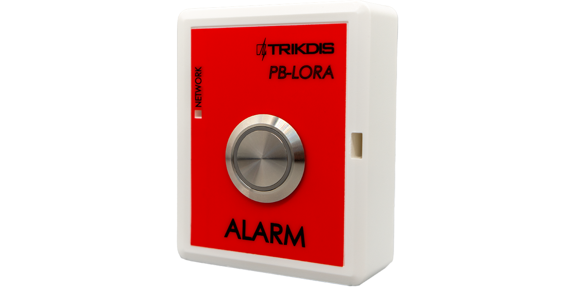
The Trikdis PB-LORA wireless panic button works with the FLEXi SP3 alarm control panel and the Protegus 2 app, for calling for help in an emergency. Because it is wireless, it can be placed anywhere, and it can also be moved.
This manual describes the 4F (433 MHz) version; it does not cover the 8F (868 MHz) versions.
Up to 250 panic buttons can be connected to one system (depending on the panel's firmware, 1.1). With a clear line of sight the range is up to 5000 metres, so it can also be used in large buildings and over large areas (factories, business sites, industrial parks).
The PB-LORA sends the emergency message by radio: the call for help is started by pressing the button. The message is received by the RF-LORA transceiver, which is connected to the FLEXi SP3 alarm control panel.
The “up to … m” distances are theoretical maximums achievable under ideal conditions. In practice, the quality and routing of the cable, sources of interference and, for radio links, walls and terrain give a considerably shorter range. Plan with a margin, and on long runs check the connection during commissioning.
1.1 What does it work with?
The PB-LORA is compatible with the FLEXi SP3 alarm control panel. It always connects through the RF-LORA transceiver: the RF-LORA is wired to the panel on the RS485 bus, and it reaches the panic button by radio.
How many PB-LORA units can connect to the panel depends on the panel's firmware:
- Up to 8 panic buttons if the panel runs firmware 1.17 or newer (for example SP3_xxxx_0117.fw). You add the buttons to the Modules list by their serial number (chapter 3). The 8 is the combined number of LoRa modules (iO-LORA, iO8-LORA, PB-LORA).
- Up to 250 panic buttons if the panel runs "release 2" firmware, version 1.16 or newer (for example SP3_xxx2_0116.fw). You enrol the buttons in the Wireless sensors window, in learning mode (chapter 4). This does not work with SP3_xxx4 firmware: with that, up to 8 panic buttons can be used.
The structure of the firmware file name is described in section 1.7 of the "FLEXi" SP3 alarm control panel – installation and programming manual.
The wiring and setup of the RF-LORA are described in the RF-LORA manual. The transceiver in the shop:
 Trikdis RF-LORA wireless expander module
1.2 Technical data
| Parameter | Value |
|---|---|
| Frequency | 433.3–434.7 MHz |
| Modulation | LoRa |
| Power supply | 3 V, CR123A battery |
| Battery life | at least 3 years |
| Current consumption | up to 0.008 mA in standby · up to 50 mA briefly, while transmitting |
| Message encryption | yes |
| Range in open space | up to 5000 m |
| Operating environment | −10 °C … +50 °C, relative humidity up to 80% (at +20 °C) |
| Dimensions | 62 × 77 × 25 mm |
| Weight | 80 g |
1.3 Parts
The indicator light, controls and battery of the PB-LORA on the front cover and on the printed circuit board:
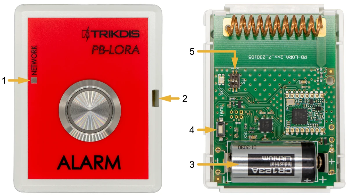
- 1 indicator light (NETWORK)
- 2 opening slot of the cover
- 3 3 V battery (CR123A)
- 4 TAMP button – pairing the device and checking the connection
- 5 SW DIP switch
The two switches of the SW DIP switch:
- Switch 1 – radio channel: OFF = RF1, ON = RF2. Change it if the current channel is heavily loaded.
- Switch 2 – modulation: OFF = fast, ON = slow. In the ON position the range roughly doubles, depending on the environment, but battery consumption increases and system performance decreases. If the link is also of good quality in the OFF position, leave it OFF.
The switch positions must match
The SW DIP switches of the PB-LORA and of the RF-LORA must be in the same position, otherwise there is no radio link.
1.4 Indicator light
The single indicator light of the PB-LORA, NETWORK, signals with flashes after a button is pressed:
| Button | Flash | Meaning |
|---|---|---|
| ALARM | 1st green | the message has been sent, the battery voltage is good |
| ALARM | 1st red | the message is being sent, the battery voltage is low |
| ALARM | 2nd red | the RF-LORA's confirmation has arrived: the message has been delivered |
| TAMP | 1st green | the message has been sent, the battery voltage is good |
| TAMP | 1st red | the message is being sent, the battery voltage is low |
| TAMP | 2nd red | the RF-LORA's confirmation has arrived: the message has been delivered |
| TAMP | 3rd–12th | the radio signal level* |
* Use it with at least four flashes.
After inserting the battery
After inserting the battery, wait at least 10 seconds before using the device.
2. Mounting and system wiring
Warining!
It is forbidden to perform wiring on a device under voltage. Before starting the work, disconnect power (including backup batteries).2.1 Mounting
You fix the base of the panic button's case in the desired place with screws:
- Remove the cover: insert a screwdriver into the opening slot of the cover (1.3, marker 2), then press its handle down to separate the front cover from the base.

- Take out the printed circuit board.
- Fix the base of the case in the desired place with screws.

- Put the printed circuit board back.
- Insert the battery (3 V, CR123A). Wait at least 10 seconds before use (1.4).
- Put the cover back.
2.2 System wiring
The PB-LORA does not need to be wired: it runs on a battery and connects to the RF-LORA transceiver by radio. Only the RF-LORA is wired, to the RS485 bus of the FLEXi SP3:
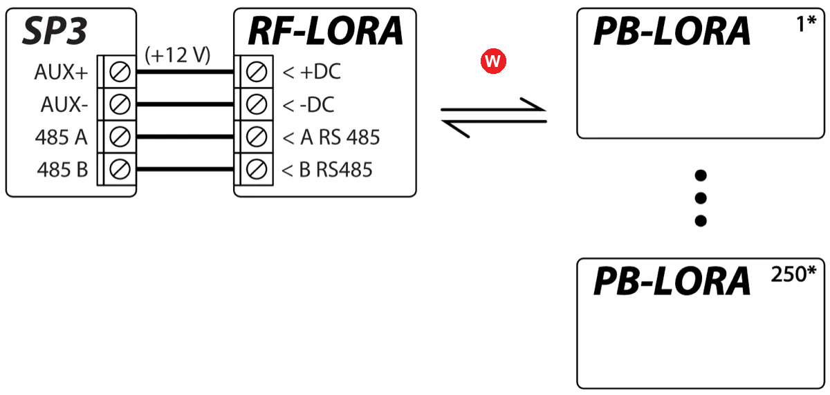
- W wireless link ("Wireless connection"), up to 5000 m ("up to 5000 m")
The “up to … m” distances are theoretical maximums achievable under ideal conditions. In practice, the quality and routing of the cable, sources of interference and, for radio links, walls and terrain give a considerably shorter range. Plan with a margin, and on long runs check the connection during commissioning.
The RF-LORA transceiver must be connected to the FLEXi SP3 alarm control panel. Up to 8 PB-LORA panic buttons can be assigned to the panel if it runs firmware 1.17 or newer (for example SP3_xxxx_0117.fw), or up to 250 if it runs "release 2" firmware 1.16 or newer (for example SP3_xxx2_0116.fw).
3. Adding it to the FLEXi SP3 (up to 8 buttons)
This method is for a FLEXi SP3 panel running firmware 1.17 or newer (for example SP3_xxxx_0117.fw): you add the panic button to the TrikdisConfig Modules list by its serial number.
All Trikdis devices can be programmed using a common software. The software is called TrikdisConfig and can be downloaded from the manufacturer's website.
After downloading, install the program. If a new version is available each time you start TrikdisConfig, download and install the recommended update!
- The RF-LORA transceiver must be connected to the FLEXi SP3 (2.2).
- Switch on the supply voltage of the FLEXi SP3.
- There must be a battery in the PB-LORA panic button.
- Start TrikdisConfig.
- Connect the FLEXi SP3 to the computer with a USB Mini-B cable, or connect to it remotely.
- Press the Read [F4] button: the program reads the panel's settings. If the program asks for it, enter the six-character administrator code.
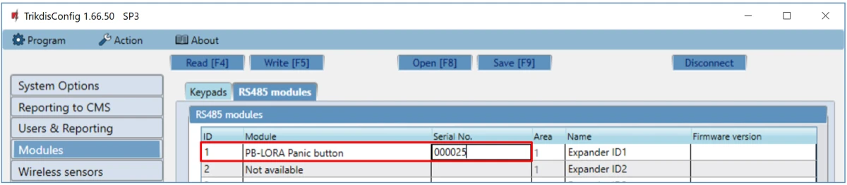
- In the Modules list, select the PB-LORA Panic button item.
- In the Serial No. field, enter the serial number of the PB-LORA.
- On the Zones tab, set up the panic button's zone.
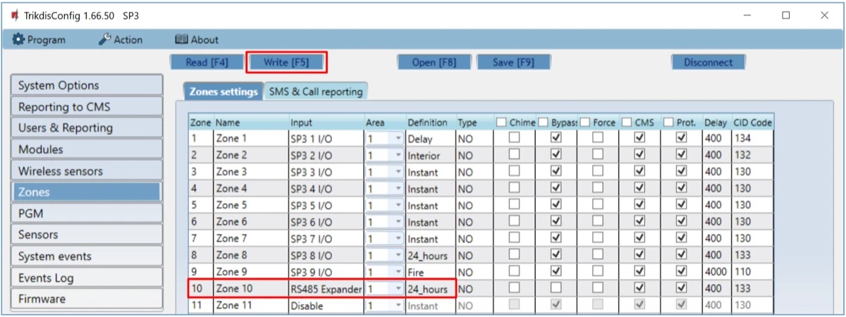
The zone functions are described in section 6.7 of the "FLEXi" SP3 alarm control panel – installation and programming manual. The factory example uses 24_hours: a zone that is always monitored; when it is violated, the siren and the strobe switch on and the event report is sent. Silent 24h is the silent version suited to panic buttons: the event report is sent immediately, but the siren and the strobe do not start.
- At the end of the setup, press the Write [F5] button.
- Wait until writing is finished.
- Press the Disconnect button and unplug the USB cable.
- Wait 1 minute, then press the ALARM button of the PB-LORA.
- Plug the USB Mini-B cable back into the FLEXi SP3.
- Press the Read [F4] button.
- The firmware version of the PB-LORA appears in the Modules window.

- Press the Disconnect button and unplug the USB cable.
While the USB cable is plugged into the Trikdis device (and the other end into the computer), the device switches to programming mode.
- Normal operation stops,
- It draws power from the USB cable,
- After unplugging, it restarts (if powered).
Deleting a panic button from the memory of the FLEXi SP3
- Start TrikdisConfig.
- Connect the FLEXi SP3 to the computer with a USB Mini-B cable, or connect to it remotely, and press the Read [F4] button.
- In the Module column of the Modules window, select Not available instead of the PB-LORA Panic button to be deleted, and press the Write [F5] button. This deletes the panic button from the panel's memory.
4. Enrolling 250 panic buttons in the FLEXi SP3
This method is for a FLEXi SP3 panel running "release 2" firmware 1.16 or newer (for example SP3_xxx2_0116.fw). It does not work with SP3_xxx4 firmware: with that, up to 8 panic buttons can be used (chapter 3). You register the RF-LORA transceiver in the Modules list, and enrol the panic buttons in the Wireless sensors window, in learning mode.
- The RF-LORA transceiver must be connected to the FLEXi SP3 (2.2).
- Switch on the supply voltage of the FLEXi SP3.
- There must be batteries in the PB-LORA panic buttons.
- Start TrikdisConfig.
- Connect to the FLEXi SP3 remotely.
Conditions for remote configuration
Remote configuration only works if, on the FLEXi SP3:
- the WiFi or LAN connection is set up, or there is an activated SIM card in it, and the PIN code is entered or disabled;
- mobile data is switched on for the SIM card;
- the Protegus cloud service is switched on;
- the supply voltage is switched on (the PWR LED flashes green);
- there is a network connection (the NET LED is steady green and flashes yellow).
- In the Unique ID field of the TrikdisConfig Remote access group, enter the IMEI number of the FLEXi SP3. The IMEI number is on the sticker on the panel and on its packaging.
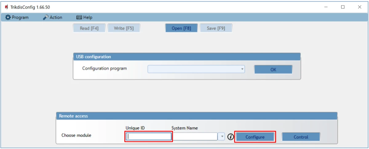
- Press the Configure button.
- Press the Read [F4] button: the program reads the panel's settings. If the program asks for it, enter the six-character administrator code.
- In the Modules list, select the RF-LORA transceiver item.
- In the Serial No. field, enter the serial number of the RF-LORA.
- Press the Write [F5] button.
- Wait until writing is finished.

- Wait 1 minute.
- Press the Read [F4] button.
- The firmware version of the RF-LORA appears in the Modules window.

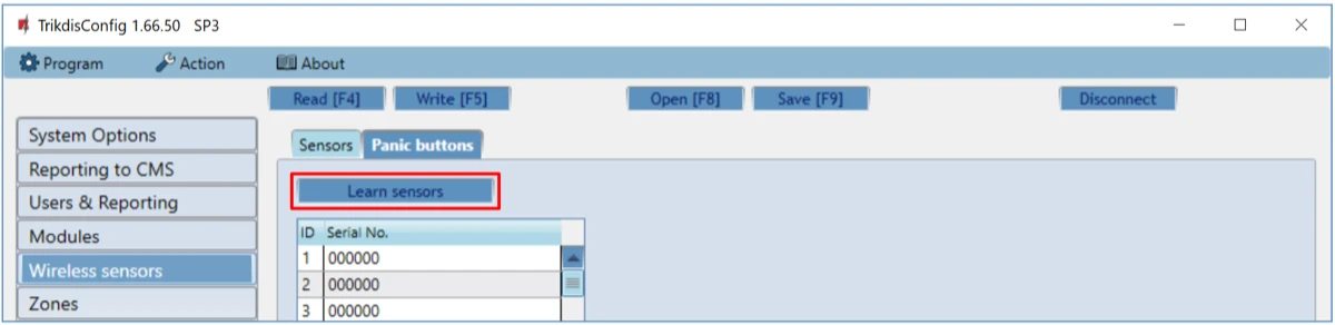
- Open the Panic buttons tab of the Wireless sensors window.
- Press the Learn sensors button.
All at once
You can also enrol all the panic buttons at once. During enrolment, the RF-LORA should be at least 1 m away from the panic buttons.
- The DATA/TROUBLE light of the RF-LORA starts flashing red and green: the transceiver switches to learning mode, and TrikdisConfig opens the panic button enrolment window.
- Briefly press the TAMP button on the printed circuit board of the PB-LORA.
- The DATA/TROUBLE light of the RF-LORA turns green for a few seconds, then continues flashing red and green.
- After a few seconds the PB-LORA appears in the list. The UID number must match the serial number on the panic button's sticker.
- For the next panic button, again briefly press the TAMP button on its printed circuit board.
- At the end of enrolment, press the Stop learning button.

- At the question ("Do you want to save new parameters to the module?"), press the Yes button: the panic buttons are written to the FLEXi SP3.
- Wait a few minutes, then press the Read [F4] button.
TrikdisConfig lists the enrolled panic buttons in the Wireless sensors window. The number in the Serial No. field must match the serial number written on the back of the panic button's case.

Deleting a panic button from the memory of the FLEXi SP3
- Start TrikdisConfig.
- Connect the FLEXi SP3 to the computer with a USB Mini-B cable, or connect to it remotely, and press the Read [F4] button.
- In the Wireless sensors window, enter 0 in the Serial No. field of the panic button to be deleted, and press the Write [F5] button. This deletes the panic button from the panel's memory.
5. Frequently asked questions
How do I know that the signal has been delivered?
Watch the NETWORK light after pressing the ALARM button: the first, green flash shows that the message has been sent, and the second, red flash shows that the RF-LORA's confirmation has arrived (1.4). If the second flash does not come, go through the points of the next question.
There is no radio link with the RF-LORA – what should I check?
- Whether both switches of the SW DIP switch are in the same position on the PB-LORA and on the RF-LORA (1.3) – with different positions there is no radio link.
- Whether there is a battery in the panic button and whether its voltage is good: with low voltage the first flash of the NETWORK light is red (1.4). After inserting the battery, wait at least 10 seconds.
- Whether the serial number in the Modules or the Wireless sensors list is correct (chapters 3 and 4).
- Check the signal level at the mounting location: remove the cover and briefly press the TAMP button. The 3rd–12th flashes of the NETWORK light show the radio signal level; at least four flashes are recommended.
- With a weak signal, set switch 2 to ON (slow modulation) on the RF-LORA and on all the LoRa modules – this roughly doubles the range, but battery consumption increases.
The NETWORK light flashes red first
The battery voltage is low: replace the battery (3 V, CR123A). The battery life is at least 3 years. After replacing it, wait at least 10 seconds before using the button.
How many panic buttons can be connected to one FLEXi SP3?
It depends on the panel's firmware: with firmware 1.17 or newer, up to 8 (in the Modules list, chapter 3); with "release 2" firmware 1.16 or newer, up to 250 (by enrolment in the Wireless sensors window, chapter 4). With SP3_xxx4 firmware, up to 8. In both cases the signals are received by the RF-LORA transceiver.
Which switch position should I choose?
By default, fast modulation (switch 2 OFF). If there is no reliable link because of the distance, slow modulation (ON) roughly doubles the range, depending on the environment, but battery consumption increases and system performance decreases. Change the channel (switch 1) if the current channel is heavily loaded. Whichever you change, set it the same way on the RF-LORA and on every LoRa module.
6. Safety instructions
Attention!
Electricity can be dangerous and may cause personal injury or DEATH, as well as other financial loss or damage if not used or installed properly.
Installation involves working with electrical equipment, and it should be executed in accordance with current regulations!
Warranty validation requires the device to be installed by a qualified person following the installation regulations for electrical equipment and adhering to the current regulations for the safe operation of electrical equipment.
- The PB-LORA panic button may only be installed and maintained by qualified persons.
- Before installation, read this manual carefully to avoid mistakes that could lead to malfunction or even damage to the equipment.
- Disconnect the power before making any connection.
- Changes, modifications or repairs not authorized by the manufacturer void the warranty.
- Do not throw the device and its parts in household waste: follow the local waste sorting regulations.
See also
- RF-LORA wireless transceiver – installation and setup manual – wiring, DIP switch and indicator lights of the transceiver.
- "FLEXi" SP3 alarm control panel – installation and programming manual – wiring and setting up the panel, including the firmware versions (1.7), the wireless devices (6.6) and the zone functions (6.7).
- Trikdis documentation: docs.trikdis.com – PB-LoRa Wireless Panic Button.