

“FLEXi” SP3 alarm control panel – installation and programming manual
Installation and programming manual for the Trikdis "FLEXi" SP3 alarm control panel: power supply, wiring zones and PGM outputs, keypads and expanders, programming in TrikdisConfig, reporting to the monitoring station, the Protegus 2 app.
- 106 min read

1. Overview
The "FLEXi" SP3 is Trikdis's intrusion and fire alarm control panel with the communicator already built in: over a Wi-Fi and/or Ethernet connection, and with a 2G / 4G modem (over the mobile network, if a SIM card is fitted), it reports every triggered event directly to the monitoring station and to the Protegus 2 app (Protegus cloud). It has ten IO terminals with selectable function (zone or PGM output), handles eight partitions, and – depending on the firmware version – can be expanded to 32 or 64 zones with keypads, iO expanders and wireless receivers. You make the settings with the TrikdisConfig software over a USB cable or remotely; the user controls the system from a wired or wireless keypad, with an iButton key, an RFID card, from the Protegus 2 app, and on the modem versions also by SMS and phone call – and can switch the protection mode of the different areas (partitions) of the building remotely too. The panel is certified to EN 50131 Grade 3.
1.1 What it is for, how it works
What it is best for
- Alarm systems for small and medium-sized buildings, preferably complemented by monitoring: it accepts both wired and wireless detectors, forwards events both to the monitoring station and to the user, and both can control it remotely.
- Replacing an existing alarm control panel: the values of the end-of-line resistors in the detectors can be set in the panel to match the replaced panel, so the detectors do not have to be rewired one by one.
- Automation alongside security: garage and garden gates, irrigation, lighting, heating, ventilation, cooling and anything else that can be switched on and off – from the PGM outputs, with operating logic, scheduling or in thermostat mode.
How it works
- It reports to the monitoring station over the built-in Wi-Fi, Ethernet or mobile network connection; with an add-on module also over an Ethernet (E485), VHF/UHF radio (T16) or Sigfox (SF485) channel, with selectable priority. Any monitoring station can receive it that has a Trikdis software or hardware IP receiver, or an IP receiver that understands the SIA DC-09 protocol. It can send to the receivers of two different security companies in parallel, each with a main and a backup receiver.
- It notifies the user in the Protegus 2 app with a push message and a separate sound signal, and the modem versions also by SMS to up to 8 phone numbers. Only the old SP3_12xx version, with firmware up to 1.13, can notify with a call carrying a pre-recorded voice message (to up to 8 phone numbers). It can be set so that an event goes first to the monitoring station and only then to the user.
- It can be controlled remotely: arming, disarming, Stay and Sleep modes, switching devices connected to the PGM outputs and monitoring the temperature from the app; on the modem versions also by SMS and phone call.
- Inputs and outputs: 10 IO terminals, each usable as an input (NC, NO, EOL, ATZ types, with adjustable resistor values in the EOL and ATZ circuits) or as an open-collector output; the number of inputs can be increased to 64 with keypads and with iO, iO-8, iO8-LORA, iO-LORA and iO-WL expanders, and the number of outputs to 16 with the same expanders; two dedicated outputs (BELL for the siren, LED for the indicator light); seven output operating modes, and to each output an operating logic, a preset schedule or, for example, thermostat mode can be assigned; on the 1-Wire bus up to 8 temperature sensors, 1 temperature and humidity sensor or an iButton reader; on the GRN / YEL keypad bus 8 keypads of the same type and the Paradox RTX3 wireless receiver (4.3); on the RS485 bus iO expanders, wireless receivers (RF-LORA, RF-SH, RF-S8, RF-HW), and the E485, T16 and SF485 modules.
- Operation: 40 user codes (1 master code and 39 normal codes, 4 or 6 digits), which can also be used as duress codes – the code disarms the alarm, but the monitoring station receives a separate signal that the disarming happened under duress. Trikdis, Paradox and Crow keypads, CZ-Dallas and TM17 iButton readers (discontinued), Wiegand 26/34 RFID readers.
- Installation and setup: metal-box kits with a built-in power supply, in several sizes, with a step-down transformer or a switch-mode power supply; the factory settings can be used without changes at most small and medium-sized sites (seven out of ten); the previous panel can be replaced without changing the detectors' resistors; the settings can be saved to a file; two access levels (installer and administrator); remotely, TrikdisConfig not only configures the panel but also shows how it is working.
1.2 Versions and type codes
The panel is a single printed circuit board, available in six versions according to the built-in communication modules. The version is indicated by the first digit (y) of the SP3_yxxz code in the firmware file name; you see the same in the TrikdisConfig status bar, and when updating only firmware with the same digit can be loaded (section 1.7).
| Version | Connection | Code (y) | SIM slot |
|---|---|---|---|
| SP3 WiFi | Wi-Fi | 2 | – |
| SP3 Ethernet | wired network (Ethernet, RJ45) | 3 | – |
| SP3 WiFi + 2G | Wi-Fi + 2G (GSM/GPRS) modem | 5 | 1 × nano-SIM |
| SP3 WiFi + 4G | Wi-Fi + 4G (LTE) modem | 1 | 1 × nano-SIM |
| SP3 Ethernet + 4G | Ethernet + 4G (LTE) modem | 6 | 1 × nano-SIM |
| SP3 Ethernet + 2 SIM 4G | Ethernet + 4G (LTE) modem, with two SIM slots | check it in the device's status bar | 2 × nano-SIM |
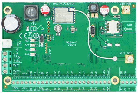
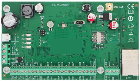
One or two communication channels. The WiFi and Ethernet versions communicate over one channel, the modem versions over two (dual path): over the mobile network as well as the wired connection.
- Over Wi-Fi and Ethernet, access from the phone is fast and there are no mobile data costs.
- If the wired internet is interrupted, or the router switches off during a power cut, the modem panel switches to the mobile network by itself.
- Thanks to the two channels backing each other up (dual path), the signal reaches its destination even if one path fails.
- Remote programming and firmware updates are convenient over the fast Wi-Fi, Ethernet and 4G connections.
The 2G modem of the modem versions works on the 850 / 900 / 1800 / 1900 MHz bands, the 4G (LTE) modem on the B1 / B3 / B7 / B8 / B20 / B28 bands used in Europe (EMEA); versions with modems for other band plans are also made for other regions (Latin America, Australia, North America) (the bands are given in the table in section 1.3). The Wi-Fi is 2.4 GHz, 802.11 b/g/n, with WPA / WPA2 encryption.
1.3 Technical data
| Property | Value |
|---|---|
| Supply voltage [AC / DC] | 16 V AC or 16–24 V DC, 2.5 A |
| Current consumption | up to 50 mA in standby; up to 200 mA briefly, while sending |
| Backup power [BAT] | 12 V lead-acid battery, 4 Ah or 7 Ah |
| Battery charging current | up to 500 mA |
| Power for external devices [AUX] | 12 V DC, up to 1 A |
| Siren output [BELL] | 1 A |
| LED output [LED] | 0.1 A |
| PGM output (IO terminal as output) | open collector, up to 0.1 A |
| Wi-Fi module | built in on the Wi-Fi versions; 2.4 GHz, 802.11 b/g/n, WPA / WPA2 / WPA mixed |
| Network setup | DHCP or manual |
| SIM card | 1 nano-SIM on the modem versions (2 on the 2 SIM version) |
| 2G (GSM/GPRS) modem bands | 850 / 900 / 1800 / 1900 MHz |
| 4G (LTE) modem bands – "FLEXi" SP3_14E / SP3_24E, EMEA and Thailand | B1 / B3 / B7 / B8 / B20 / B28 |
| 4G (LTE) modem bands – "FLEXi" SP3_24S, Latin America / Australia / New Zealand | B1 / B3 / B4 / B5 / B7 / B8 / B28 |
| 4G (LTE) modem bands – "FLEXi" SP3_24A, North America | B2 / B4 / B12 |
| Event destinations | main and backup receivers of 2 security companies; the Protegus cloud, the iOS / Android Protegus 2 app; SMS to 8 phone numbers; calls to 8 phone numbers – if the user answers, the panel tells what happened with a voice message (only the SP3_12xx version, with firmware up to 1.13) |
| Event channels | GPRS or 4G, Wi-Fi, Ethernet (built in or with the E485 module), SMS; voice call to up to 8 phone numbers (only the SP3_12xx version, with firmware up to 1.13); VHF/UHF radio (with the T16 communicator); Sigfox (with the SF485 module) |
| Connection with the monitoring station | TCP/IP or UDP/IP, or SMS |
| Event coding | Contact ID |
| Encryption | TRK AES-128, SIA IP AES-128 |
| Internal clock | yes |
| Message buffer | 60 events |
| Event log | up to 1000 events; when full, the oldest is deleted |
| User codes | 40 (4 or 6 digits) |
| Duress code | one of two input modes can be selected during programming |
| Dual-function terminals [IO] | 10; IN or OUT function set during programming. As input: NC, NO, EOL, EOL_T, 3EOL, ATZ, ATZ_T. As output: open collector (OC), up to 100 mA |
| Partitions | 8 |
| Zones | 10 (20 with ATZ zone doubling); up to 64 with expanders (section 1.7) |
| PGM outputs | 2 (12 if the IO terminals are set as outputs; 16 with expanders) |
| Keypads | up to 8 (the types are listed in section 1.4) |
| RFID readers (Wiegand 26/34) | up to 2 |
| 1-Wire bus length [1 WIRE] | up to 30 m |
| Temperature sensors | Maxim / Dallas DS18S20, DS18B20; AM2301 series |
| Number of temperature sensors on the 1-Wire bus | 8 (Dallas) or 1 (AM2301) |
| Electronic (iButton) keys [1 WIRE] | Maxim / Dallas DS1990A, up to 40 keys |
| RS485 bus length | up to 100 m |
| Devices on the RS485 bus | up to 8 |
| Operating environment | −10 °C … +50 °C, up to 80 % relative humidity at +20 °C, without condensation |
| Board dimensions | 117 × 79 × 25 mm; the Ethernet + 4G versions 137 × 79 × 25 mm |
| Weight | 0.1 kg |
The “up to … m” distances are theoretical maximums achievable under ideal conditions. In practice, the quality and routing of the cable, sources of interference and, for radio links, walls and terrain give a considerably shorter range. Plan with a margin, and on long runs check the connection during commissioning.
1.4 Compatible modules and keypads
The panel's AUX output supplies up to 1 A to external devices; to size the backup battery (section 2.1), add up the combined current consumption of the connected modules. The factory list:
| Module | Current consumption |
|---|---|
| SK-LED TouchPad keypad (Protegus SK232 LED W) | 60–150 mA |
| SK-LCD TouchPad keypad (FLEXi SK232LCD – in the shop: FLEXi LCD keypad) | 25–60 mA |
| SK LCD Button keypad | up to 70 mA |
| SK LED Button keypad | up to 70 mA |
| Paradox K636 keypad | 40–70 mA |
| Paradox K10H(V) keypad | 44–72 mA |
| Paradox K32 LED, K32+ LED keypad | 49–148 mA |
| Paradox K32LCD+ keypad | 70–150 mA |
| Paradox K35 keypad | 30–70 mA |
| Paradox TM50 keypad | 100–230 mA |
| Paradox TM70 keypad | 200–330 mA |
| Crow CR16, CR-LCD keypad | 40–75 mA |
| iO-8 expander | up to 20 mA |
| iO expander | up to 50 mA |
| iO-MOD – iO-WL wireless transceiver | 50–150 mA |
| iO-WL wireless expander | up to 200 mA |
| RF-SH wireless receiver (for Crow detectors) | up to 100 mA |
| Paradox RTX3 wireless transceiver | up to 200 mA |
| RF-HW wireless transceiver (for Honeywell detectors) | up to 100 mA |
| RF-S8 wireless transceiver (for S8 detectors) | up to 100 mA |
| RF-LORA wireless transceiver (for LORA detectors and modules) | 50–150 mA |
| iO-LORA, iO8-LORA expander | up to 50 mA |
| PB-LORA panic button | own battery, 3 V CR123A |
| REL-LORA relay module | up to 45 mA |
| E485 Ethernet module | 50–150 mA |
| TM17 iButton reader | up to 50 mA |
| CZ-Dallas iButton reader | up to 25 mA |
| T16 VHF / UHF radio communicator | 100 mA – 1.2 A |
| RFID reader (Wiegand 26/34) | up to 100 mA |
Keypads. Up to 8 keypads of the same type can be connected to the GRN / YEL bus:
Trikdis PROTEGUS SK232LED, FLEXI LCD, FLEXI LED, SK-LCD Button, SK-LED ButtonParadox K32LCD+, K32+, K32LED, K32+ LED, K35, K10H, K10V, K636, TM50*, TM70*
Crow CR16, CR-LCD
LED keypads display the status of the first 2 areas only, but can control all 8 areas.
*This keypad can only arm/disarm the first 2 areas.
Wireless devices. The type of wireless receiver depends on the panel's firmware version (section 1.7): a panel works with one kind of receiver at a time.
You can add wireless sensors and devices to your FLEXi SP3 alarm system


By connecting a TRIKDIS RF-LORA or a Paradox RTX3 wireless expander interface you can extend the "classic" wired alarm system as hybrid or wireless. Comes handy when you have no option to lay new wires and need wireless sensors or other equipment.
You can use the Trikdis wireless extenders, sensors and devices with the TRIKDIS RF-LORA.
You can use the Paradox sensors and devices and keypads with the RTX3.
1.5 Parts of the board and its terminals
The drawing shows the main parts of the board; the function of the terminals is listed in the table below the drawing.
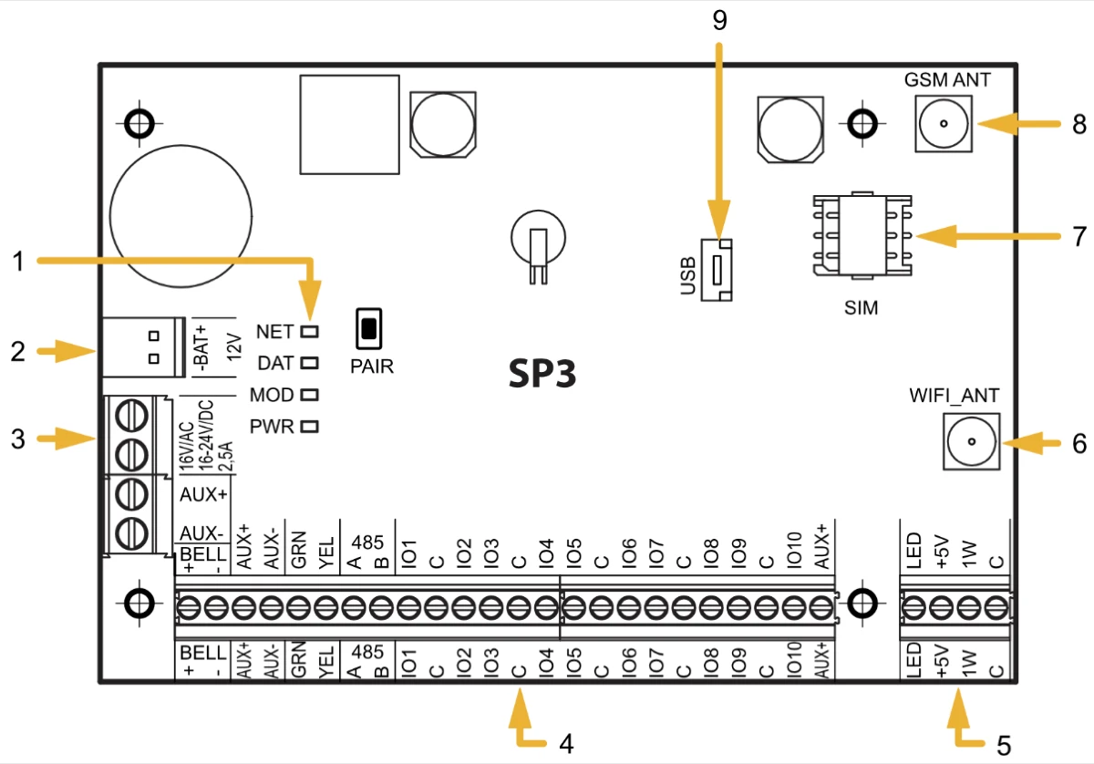
- 1 Connection and operation indicator LEDs (section 1.6)
- 2 Terminal for the backup power supply (battery)
- 3 Terminal for the main power supply
- 4 Terminal for external devices
- 5 Terminal for the 1-WIRE data bus
- 6 SMA connector for the Wi-Fi antenna
- 7 Nano-SIM slot
- 8 SMA connector for the mobile network antenna
- 9 USB Mini-B socket for programming
| Terminal | Function |
|---|---|
| AC/DC (2 terminals) | Main power: 16 V AC, or the positive and negative poles of 16–24 V DC |
| BAT+ | Positive pole of the backup power supply (12 V battery) |
| BAT− | Negative pole of the backup power supply |
| AUX+ | +12 V for external devices (up to 1 A) |
| AUX− | Common negative |
| BELL+ | Siren output: +12 V for the siren |
| BELL− | Siren output: switched negative pole of the siren (up to 1 A) |
| GRN | Keypad bus (data) |
| YEL | Keypad bus (data) |
| A 485 | A wire of the RS485 bus |
| B 485 | B wire of the RS485 bus |
| IO1 – IO9 | Inputs/outputs (factory setting: input) |
| IO10 | Input/output (factory setting: PGM output, fire detector reset) |
| C | Common negative |
| LED | PGM output (factory setting: system status indication) |
| +5 V | +5 V supply for 1-Wire devices |
| 1 WIRE | 1-Wire data bus |
| C | Common negative |
The terminal blocks are removable, so you can connect the wires without the board, and the board can be lifted out for servicing.
1.6 LED indications
| LED | Indication | Meaning |
|---|---|---|
| NET | flashing green | the SIM card is registering on the mobile network |
| steady green | the SIM card has registered on the mobile network | |
| flashing yellow | mobile network signal strength with 0–5 flashes; 3 is already enough | |
| DAT | off | no unsent events |
| steady green | message sending in progress | |
| steady yellow | unsent events are waiting in the buffer | |
| MOD (Wi-Fi version) | flashing green | connecting to the Wi-Fi network |
| steady green | connected to the Wi-Fi network | |
| ETH (Ethernet version) | flashing green | no LAN cable, or DHCP error |
| steady green | connected to the wired network | |
| PWR | flashing green | no operating fault |
| 1 red flash | no SIM card | |
| 2 red flashes | wrong SIM card PIN code | |
| 3 red flashes | cannot connect to the mobile network | |
| 4 red flashes | cannot reach the monitoring receiver on channel 1 | |
| 5 red flashes | cannot reach the monitoring receiver on channel 2 | |
| 6 red flashes | the internal clock is not set | |
| 7 red flashes | low backup power (battery) voltage | |
| 8 red flashes | no mains (AC) power | |
| 9 red flashes | cannot connect to the Wi-Fi network |
Troubleshooting is covered in chapter 10.
1.7 Firmware versions
The panel's firmware file name has the form SP3_yxxz_NNNN.fw. The y is the hardware version (section 1.2) – it cannot be changed when updating. The z specifies the type of wireless receiver and with it the number of zones that can be handled; you choose this when updating, matching it to the wireless receiver used. NNNN is the firmware version number; it is generally best to use the highest version.
| Firmware (z) | Wireless receiver | Wireless detectors | Zones | Keypads | Modules |
|---|---|---|---|---|---|
| SP3_xxx0 | RF-SH (discontinued), RF-LORA | Crow | 32 | Trikdis (FLEXi), Paradox, Crow CR Icon / LCD (ST) | iO, iO-8, iO-WL, iO-MOD, TM17, E485, T16, SF485, RF-LORA, iO-LORA, iO8-LORA, PB-LORA, REL-LORA, RF-SH |
| SP3_xxx1 | Paradox RTX3, RF-LORA | Paradox | 32 | Trikdis (FLEXi), Paradox, Crow CR Icon / LCD (ST) | iO, iO-8, iO-WL, iO-MOD, TM17, E485, T16, SF485, RF-LORA, iO-LORA, iO8-LORA, PB-LORA, REL-LORA |
| SP3_xxx2 | RF-HW, RF-LORA | Honeywell (345 MHz, not used in Europe) | 64 | Trikdis (FLEXi), Paradox, Crow CR Icon / LCD (ST) | iO, iO-8, iO-WL, iO-MOD, TM17, E485, T16, SF485, RF-LORA, iO-LORA, iO8-LORA, PB-LORA, REL-LORA, RF-HW |
| SP3_xxx4 | RF-LORA, RF-S8 | MAXIMUM (M4), S8 (Heyi) | 64 | Trikdis (FLEXi), Paradox | iO, iO-8, iO-WL, iO-MOD, TM17, E485, T16, SF485, RF-LORA, iO-LORA, iO8-LORA, PB-LORA, REL-LORA, RF-S8 |
The SP3_xxx4 firmware is only needed for the wireless detectors: with it, the MAXIMUM (RF-LORA) and S8 (RF-S8) wireless devices work, with 64 zones. At least version 1.21 is required, and 1.22 for the S8 devices. The LORA expanders connected via the RF-LORA (iO-LORA, iO8-LORA, PB-LORA, REL-LORA) work with all four versions. The Paradox RTX3 expander requires SP3_xxx1, with 32 zones. Always load the latest version: in November 2026 this is 1.27, with improved communication, and the sending of too many SMS messages has been fixed in it. The coding and the rules for choosing are described in a separate article: FLEXi SP3 firmware: how to choose the right one?. The update steps are in chapter 9.
2. Power supply and quick start
The panel, and with it the whole alarm system, is powered by a mains power supply, with a 12 V battery as backup. In this chapter you will find the rules of the power supply, the factory kits and a short order of the commissioning steps; the details of the wiring are in chapters 3 and 4, those of the settings in chapters 5 and 6.
2.1 Mains power supply
The panel works from 16 V AC or 16–24 V DC, from a source with a load capacity of at least 2.5 A. With alternating current it is powered from the mains by a Class II step-down transformer, with direct current by a 16–24 V switch-mode power supply (in the K01 and K02 boxes available from us, a Mean Well APV-35-24). You connect the main power to the two AC/DC terminals of the board; with direct current, the positive and negative poles in the order marked at the terminals. In both cases – with AC and with DC power – connecting the backup power supply, a 12 V battery, is mandatory, so that the power supply stays continuous without interruption (section 2.2).
Circuit breaker and earthing
A two-pole automatic circuit breaker with a contact gap of at least 3 mm must be installed in the power circuit; the switch must be in a place known to and accessible by the technician servicing the panel. With a metal box, earth the box. The box, the power supply, the battery and the programming device must comply with the EN 60950 standard.
Current requirement calculation. According to EN 50131, after the mains power fails the backup power supply must operate the system for 12 hours (Grade 2) or 60 hours (Grade 3). For this, add up the panel's standby current (50 mA) and the current consumption of the connected keypads, modules, detectors and signalling devices – the data of Trikdis and supported third-party devices is given in the table in section 1.4 – and choose the battery capacity accordingly. The AUX+ terminal can supply at most 1 A in total to external devices; if more is needed, use a separate power supply with a common negative.
2.2 Battery
The backup power supply is a 12 V lead-acid battery, 4 Ah or 7 Ah (at least 7 Ah for Grade 3), connected to the BAT+ / BAT− terminals of the board with the connecting cable supplied in the box. The panel charges it with up to 500 mA.
- If the mains power fails, the panel sends an AC Fault event and switches to the battery.
- At 11.5 V a Low Battery event is generated; below 9.5 V the panel disconnects the battery to protect it from deep discharge.
- When the mains power returns, it sends an AC Restore event and starts charging; at 12.6 V it sends a Battery Restore event.
To meet the Class II requirement the battery must be charged within 72 hours, for Class III within 24 hours – this results from the battery capacity together with the 500 mA charging current.
2.3 Package contents, boxes: K01 and K02
The panel is available on its own (board) or with a prepared metal box. The factory package of the board contains: the "FLEXi" SP3 board, a battery connecting cable, 20 pcs 2.2 kΩ and 10 pcs 4.7 kΩ resistors, 4 plastic spacers for mounting, and for the modem versions the ME301M magnetic-base antenna with 2.5 m cable (2 pcs according to the factory packing list). The USB Mini-B cable needed for programming and the battery are not included in the package.
In the boxed versions the panel is mounted in a metal box with a tamper switch, with a prepared power supply: Mean Well APV-35-24 switch-mode power supply, the 230 V mains connection point with a 3.15 A fuse, everything pre-wired. There are two box sizes:
| Box | Size | Note |
|---|---|---|
| K01 – standard-size metal box | 285 × 280 × 80 mm | for all SP3 versions |
| K02 – small metal box | 200 × 210 × 80 mm | the Ethernet + 4G version does not fit in it |
 Normal size metal box with PSU for FLEXi SP3 control panel
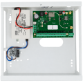 Small size metal box with PSU for FLEXi SP3 control panel
Both boxes (K01 and K02) contain a Mean Well switch-mode power supply with a terminal block with a 3.15 A fuse; older K01 boxes still had a 230 V / 16 V, 40 VA transformer. The factory kits (SP3 KIT, SP3 KITi) come with the board mounted in the metal box plus 2 ME301M antennas (with 2.5 m cable), a battery connecting cable, 20 pcs 2.2 kΩ and 10 pcs 4.7 kΩ resistors, and a tamper sensor.
2.4 Commissioning steps in brief
What you will need
USB Mini-B cable · flat screwdriver for the terminals · the 2.2 kΩ and 4.7 kΩ resistors supplied in the box · 12 V 7 Ah battery · for the modem version an active nano-SIM with mobile data service (switch off the PIN request beforehand in a phone) · for the Wi-Fi version the network name and password · the TrikdisConfig software on a Windows computer.

- 1 Screwing the mobile and Wi-Fi antennas onto the antenna connectors
- 2 Inserting the nano-SIM card into the SIM slot
- 3 Connecting the devices to the terminals
- 4 Connecting the mains power to the AC/DC terminals
- 5 Connecting the battery to the BAT+ / BAT− terminals
- Plan the system. Mark the locations of the box, the keypads, the sounders and flashers and the controlled devices; based on the area to be protected and the characteristics of the detectors, decide on the number, type and location of the detectors.
- Mount the board in the box with the plastic spacers, and earth the metal box (section 3.1).
- Screw on the antennas (mobile and Wi-Fi), and insert the activated nano-SIM card (modem version).
- Connect the devices according to the wiring diagrams: opening detectors, motion, fire and other detectors (3.2–3.3), siren (3.4), keypads and readers (3.5–3.6), temperature sensor (3.7), relays and indicator light (3.8), the box's tamper switch; expanders and wireless receivers according to chapter 4.
- Switch on the mains power at the AC/DC terminals. On power-up the panel recognises the keypads, expanders and readers correctly connected to the 1-WIRE and GRN / YEL buses (section 3.9).
- Connect the battery to the BAT+ / BAT− terminals.
- Set up the panel with TrikdisConfig over the USB cable (chapter 6). The factory settings are fine for most small and medium-sized sites; what typically needs reviewing: partitions and the basic system data (System Options, 6.2), zone type and behaviour (Zones, 6.7), users, their codes and phone numbers (Users & Reporting, 6.4), the exact time (6.2), the SIM card data (6.2), the monitoring receivers – switched off by default (Reporting to CMS, 6.3) –, the Protegus cloud – switched on by default – and the SMS notifications (6.4, 6.10), the operation of the PGM outputs (6.8). The recommended settings in detail:
- System. If you want to arm the zone groups separately, divide the system into partitions and set the partitions' properties (6.2.2). Set every zone according to the detector's characteristics and the alarm behaviour wanted for the zone's event (6.7); in a system divided into partitions you assign every zone to the desired partition. For operation from the keypad, with an iButton key or from a phone (by SMS), users must be created and given permissions (6.4).
- Message sending. The exact time must be set so that messages get the correct timestamp (6.2.1). Event reporting is enabled for all events by default: if an event occurs, its report goes to the set recipients over the set channels; you can disable the reporting of individual events in the System events window (6.10). If the panel sends over the mobile network, enter the SIM card data (6.2.1). Reporting to the monitoring station is switched off by default (6.3). The Protegus cloud is switched on by default, SMS notification and calls are off by default; setting up sending to the user's phone is in section 6.10.
- Remote control. The system can be controlled by call and SMS by anyone whose phone number is in the list of users (6.4). By call, not only can the whole system or part of it be armed and disarmed, but devices connected to the PGM outputs can also be switched on and off – what needs to be set on the output for this is described in section 5.4. By SMS, some operating parameters of the panel can also be changed, the whole system or part of it can be armed and disarmed, and devices connected to the PGM outputs can be switched – the list of commands is in section 5.3.
- Replace the factory codes with values known only to you: the master code in the Users & Reporting window, the SMS password in the SMS Password field of the System Options → Access group, and the TrikdisConfig access codes in the same Access group.
- Connect the system to the Protegus 2 app (section 5.1).
- Check the operation according to chapter 8: an event from the keypad, its arrival at the monitoring station and in Protegus 2, outputs, remote arming.
3. Installation and wiring
Warining!
It is forbidden to perform wiring on a device under voltage. Before starting the work, disconnect power (including backup batteries).This chapter describes mounting the board, the order of the wiring, and then connecting detectors, smoke detectors, sirens, keypads and readers, temperature sensors and relays. The meaning of the terminals is given in the table in section 1.5; the wiring of expanders and wireless modules is in chapter 4. On the drawings, the SP3 terminal names are on the left and those of the connected device on the right.
3.1 Recommended order of installation
Planning the system:
- Sketch the floor plan of the premises and mark where the panel's box, the keypad or keypads, the sounders and flashers, and the equipment controlled automatically or remotely by the panel will go.
- Based on the site, the security requirement and the characteristics of the candidate detectors, decide on the number, type and location of the detectors.
3.1.1 Mounting the board in the box
The board belongs in a box that already has the step-down transformer (with a 500 mA fuse) and room for the backup battery. Fix the board in the chosen plastic or metal box with plastic spacers; a metal box must be earthed. The box must comply with the requirements of the EN 60950 and EN 50131 standards.

- 1 the SP3 printed circuit board ("SP3 circuit board")
- 2 spacer ("Spacer")
- 3 the box ("Box housing")
The board measures 116.5 × 78.5 mm. The centres of the four Ø4 mm mounting holes are 93 mm apart horizontally and 61 mm apart vertically; the left-hand holes are 5 mm from the left edge, the lower ones 10 mm from the bottom edge.

3.1.2 Order of connecting the devices
Connect the devices in the order below; always connect the power and the battery last.

- 1 GSM and Wi-Fi antenna on the antenna connectors
- 2 nano-SIM card in the SIM slot
- 3 the devices on the external terminal block
- 4 mains power on the AC/DC terminals
- 5 battery on the BAT+ / BAT− terminals
- Screw the GSM and Wi-Fi antennas onto the antenna connectors (one or both, depending on the version, section 1.2).
- On a modem version, insert the activated nano-SIM card into the slot. It is worth switching off the PIN request beforehand in a phone.
- On an Ethernet version (SP3_3E, SP3_44E), plug the LAN cable into the RJ45 connector.
- Based on the wiring drawings given here, the connected devices' own wiring drawings and the plan, connect the door and window opening detectors, the motion, fire and other detectors, the sounders and flashers, the keypads and the controlled devices. Also connect the tamper switch for the box door and for removal from the wall to the board's terminals.
- Connect the wires of the mains power supply to the board's AC/DC terminals and switch on the power. The panel recognises the keypads, expanders and interfaces correctly connected to the 1-WIRE and YEL/GRN buses.
- Put the battery in the box and connect its lugs to the BAT+ / BAT− terminals.
The battery must be charged within 72 hours for the system to meet security grade 2 (Grade 2), and within 24 hours for grade 3 (Grade 3).
The terminal block can be pulled off: this way the device can be de-energised or restarted in one movement, it is easier to handle during wiring, and for USB programming the device can be taken to the computer.
The recommended order of the settings (partitions, zones, users, time, reporting, remote control, changing the codes) is summarised in section 2.4, the details in chapter 6.
3.2 Connecting detectors
On the board, 10 IO terminals (IO1–IO10) accept the detector circuits. By default IO1–IO9 are inputs and IO10 is a PGM output (fire detector reset, see 3.3). The number of inputs can be increased to at most 64 with expanders (iO, iO-8, iO-WL, RF-SH, iO-LORA, iO8-LORA). Any terminal can be set as an input (zone), and the zone's properties can be set on the Zones page (6.7): the circuit type (NO, NC, EOL, EOL_T, 3EOL, ATZ, ATZ_T), the sensitivity to short circuit events, and the zone function (delay, instant, instant stay, follower, follower stay, fire, keyswitch, 24-hour, silent, silent 24-hour). The iO-8 and iO8-LORA expanders support all of the panel's circuit types.
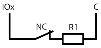
End-of-line resistors. For EOL, EOL_T, 3EOL, ATZ and ATZ_T circuits you can choose from seven resistor sets in TrikdisConfig (System Options → System general → EOL Type, 6.2.1), so when replacing an old panel the existing resistors can stay in the detectors. RT is the tamper circuit resistor, R1 the first and R2 the second detector's resistor (with 3EOL, that of the masking circuit). Next to each set are the alarm control panels whose factory resistor values match it:
| Set | RT | R1 | R2 |
|---|---|---|---|
| 1 – Trikdis default: Bosch AMAX, Risco LightSYS Plus, Satel INTEGRA (EOL) | 2.2 kΩ | 2.2 kΩ | 4.7 kΩ |
| 2 – Paradox, Honeywell Galaxy Flex, Hikvision AX Hybrid PRO (3EOL) | 1 kΩ | 1 kΩ | 2.2 kΩ |
| 3 – DSC PowerSeries, Eldes ESIM364 | 5.6 kΩ | 5.6 kΩ | 3.3 kΩ |
| 4 – Eldes ESIM364 (6-zone mode, with tamper) | 5.6 kΩ | 3.3 kΩ | 5.6 kΩ |
| 5 | 3.3 kΩ | 6.8 kΩ | 3.3 kΩ |
| 6 – Crow Runner, Texecom Premier Elite, Pyronix Enforcer | 2.2 kΩ | 4.7 kΩ | 8.2 kΩ |
| 7 | 4.7 kΩ | 4.7 kΩ | 2.2 kΩ |
For the named brands the tamper and detector resistors (RT, R1) match; for the Satel INTEGRA, the single-resistor (EOL) wiring. With zone doubling (ATZ) and 3EOL wiring, R2 must match as well: this is the case for Paradox and Hikvision AX Hybrid PRO with set 2, for Eldes ESIM364 with set 3, and for Crow Runner with set 6. Where the resistor value was adjustable in the old panel (for example Crow, Risco, Honeywell Galaxy, Pyronix, Texecom), the resistor in the detectors decides. The Honeywell VISTA (2 kΩ) and the Satel two-resistor (2EOL, 2 × 1.1 kΩ) wiring do not match any of the sets.
3.2.1 Wiring drawings
In the figures IOx is the chosen IO terminal, C the common negative terminal; NC is a normally closed, NO a normally open contact.
Markings on the drawings. R1, R2, RT – resistor; RT is the tamper circuit resistor. The red T marks the tamper contact, the blue number the detector's number; the meaning of every marking is also given below the drawing concerned.
NO – normally open, without an end-of-line resistor. When the detector is activated, it closes the circuit between IOx and C.

NC – normally closed, without an end-of-line resistor. When the detector is activated, it breaks the circuit between IOx and C.
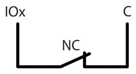
EOL – with an end-of-line resistor. With an NO detector R1 is in parallel with the contact, with an NC detector in series with it, between IOx and C; this way the panel also detects a broken wire and a short circuit.

EOL_T – with an end-of-line resistor, with tamper and wiring fault detection. Starting from IOx, the NC tamper contact and RT in series, then the NC alarm contact in parallel with R1 between RT and C.
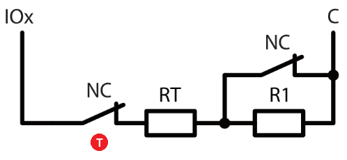
- T tamper contact ("Tamper"), signals the opening of the detector's housing
ATZ – zone doubling. Two detectors on one terminal: two circuits in series between IOx and C, in the first an NC contact in parallel with R1, in the second an NC contact in parallel with R2. This way 20 zones can be handled on the 10 terminals.

- 1 circuit of detector 1 ("Detector terminal 1")
- 2 circuit of detector 2 ("Detector terminal 2")
ATZ_T – zone doubling with tamper and wiring fault detection. Like ATZ, but in the circuit of both detectors the NC tamper contact is also in series, in the first circuit together with the RT resistor.

- T tamper contact ("Tamper"), signals the opening of the detector's housing
- 1 circuit of detector 1 ("Detector terminal 1")
- 2 circuit of detector 2 ("Detector terminal 2")
3EOL – three end-of-line resistors: alarm, tamper and masking. Within one detector, the tamper, alarm and anti-masking circuits can be recognised separately.
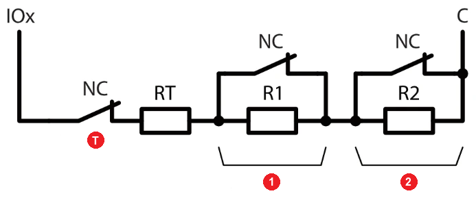
- T tamper contact ("Tamper"), signals the opening of the detector's housing
- 1 alarm circuit ("Alarm")
- 2 anti-masking circuit ("Anti-masking"), signals that the detector has been covered
3.3 Connecting smoke detectors
Two-wire smoke detectors on the LED output. If you connect the fire detectors this way, tick the LED out as 2Wire fire box on the System Options page (6.2).
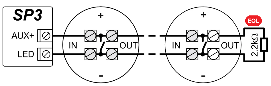
- EOL 2.2 kΩ end-of-line resistor ("End of line resistor")
Four-wire smoke detectors. Assign the fire zone function to the input (IOx) of the smoke detector circuit (6.7). The power of the four-wire detectors is switched by the IO10 PGM output, which has the Fire Sensor Reset function (6.8) – this is the factory setting of IO10. Relay K1 signals a broken wire and the removal of a detector.

- R relay K1 ("Relay")
- EOL the R1 end-of-line resistor ("End of line resistor")
Two-wire smoke detectors with the SM1 interface. With the SM1 interface, two-wire detectors can be connected to an IO input; here too relay K1 signals a broken wire and the removal of a detector. The supervision circuit can be built in two ways:
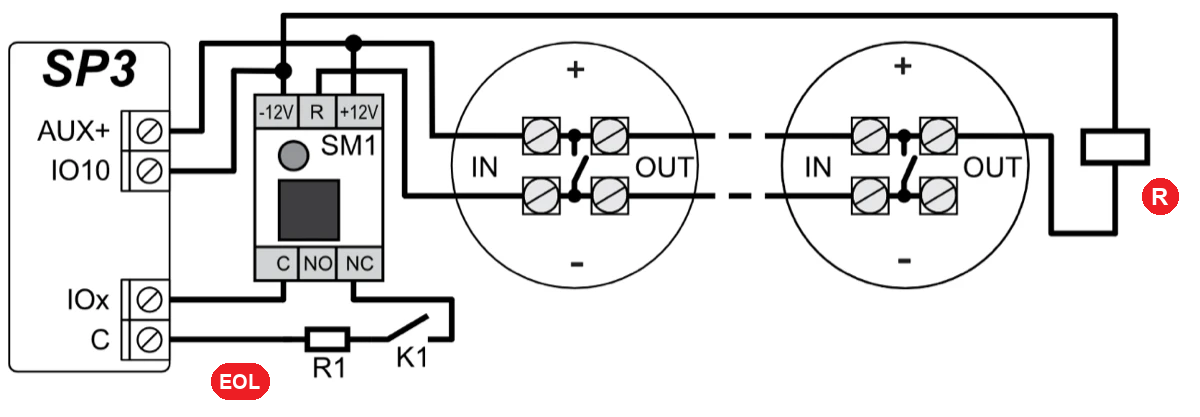
- R relay K1 ("Relay")
- EOL the R1 end-of-line resistor ("End of line resistor")

- R relay K1 ("Relay")
- EOL the R1 end-of-line resistor ("End of line resistor")
3.4 Connecting a siren
Connect the siren to the BELL+ / BELL− output (the load capacity of the BELL output is 1 A, see the technical data in section 1.3).
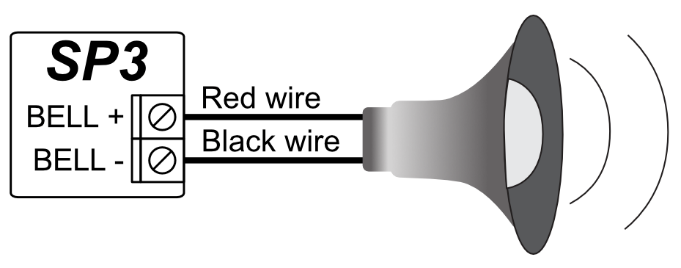
With the MR100 outdoor siren, the tamper circuit (SAB) is also supervised by the panel: by default with a 2.2 kΩ EOL, on the IO9 input. IO9 is a 24-hour zone by default, but can be changed freely. If you monitor the siren's tamper circuit with a different EOL mode in the panel, close the JPS1 contacts and connect a resistor of suitable value in series in the tamper circuit.

3.5 Connecting keypads and RFID readers
This covers keypad-bus keypads and RFID readers with the Wiegand 26/34 protocol. Up to 8 keypads of the same type can be connected to the keypad bus (GRN, YEL). Set the keypad type on the Modules page (6.5); the panel recognises and assigns the connected devices automatically. The keypad also has its own zone input (ZONE): the other end of a detector connected here goes to the AUX− terminal. Operating the system from the keypads (user codes, zone bypass, iButton and RFID, calls, SMS, PGM outputs) is described in the separate SP3 user manual for the Protegus and Paradox keypads.
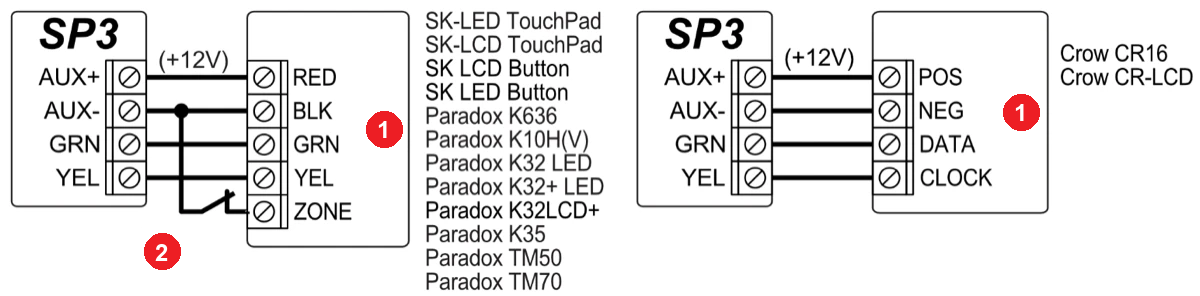
- 1 keypad ("Keypad")
- 2 the keypad's zone ("Keypad zone")
RFID reader (Wiegand 26/34). Up to 2 readers can be connected to the panel. The reader's data wires (D0, D1) go either to the keypad bus (GRN, YEL) or to the IO1 and IO2 terminals, as shown in the figures. If there are two readers (entry and exit side), no keypad can be connected to the panel.
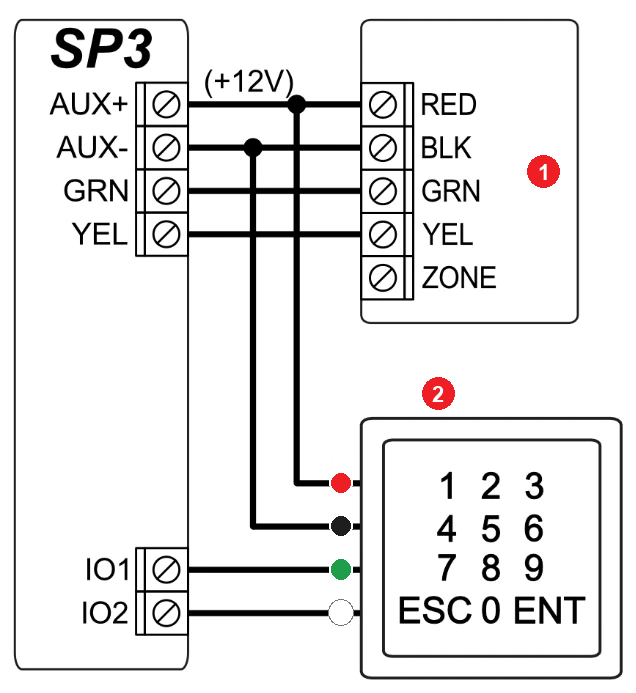
- 1 keypad ("Keypad")
- 2 entry reader: RFID reader with keypad, Wiegand 26/34 ("Entry reader", "RFID reader with keypad (Wiegand 26/34)")
- red wire, +U ("R - red wire (+U)")
- black wire, GND ("B - black wire (GND)")
- green wire, D0 ("G - green wire (D0)")
- white wire, D1 ("W - white wire (D1)")
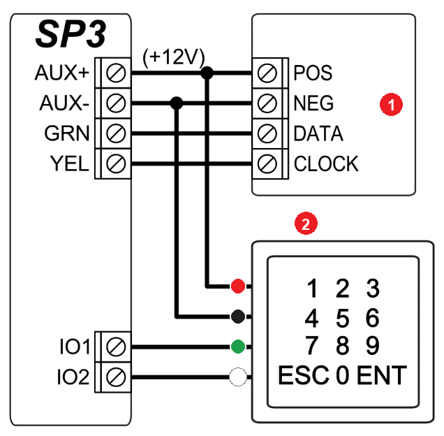
- 1 keypad ("Keypad")
- 2 entry reader: RFID reader with keypad, Wiegand 26/34 ("Entry reader", "RFID reader with keypad (Wiegand 26/34)")
- red wire, +U ("R - red wire (+U)")
- black wire, GND ("B - black wire (GND)")
- green wire, D0 ("G - green wire (D0)")
- white wire, D1 ("W - white wire (D1)")

- 1 entry reader: RFID reader with keypad, Wiegand 26/34 ("Entry reader", "RFID reader with keypad (Wiegand 26/34)")
- red wire, +U ("R - red wire (+U)")
- black wire, GND ("B - black wire (GND)")
- green wire, D0 ("G - green wire (D0)")
- white wire, D1 ("W - white wire (D1)")

- 1 entry reader ("Entry reader")
- 2 exit reader ("Exit reader")
- red wire, +U ("R - red wire (+U)")
- black wire, GND ("B - black wire (GND)")
- green wire, D0 ("G - green wire (D0)")
- white wire, D1 ("W - white wire (D1)")
3.6 Connecting TM17 and CZ-Dallas key readers
Discontinued accessory
The TM17 iButton key reader is a discontinued accessory and is no longer available. The description has been kept for existing systems.
The CZ-Dallas iButton key reader connects to the 1 WIRE bus, with a wire of up to 30 m. The TM17 reader connects to the RS485 bus, with a wire of up to 100 m.
"Up to 30 m" and "up to 100 m" are theoretical maximums under ideal conditions – see the note in section 1.3.
For the CZ-Dallas light indication, set the type of the LED output to System state (6.8): with the system armed, the reader's ring is red, with it disarmed, yellow.

- brown wire, RED LED+ ("Brown wire", "RED LED+") – the red light
- green wire, GREEN LED+ ("Green wire", "GREEN LED+") – the green light
- yellow wire, LED− ("Yellow wire", "LED-")
- white wire ("White wire")
- grey wire ("Gray wire")

- red wire ("Red wire")
- blue wire ("Blue wire")
- black wire ("Black wire")
- white wire ("White wire")
3.7 Connecting temperature sensors
Up to 8 Maxim / Dallas DS18S20 or DS18B20 temperature sensors, or 1 AM2301 temperature and humidity sensor, can be connected to the 1 WIRE bus; the panel recognises and assigns them automatically, and the values are shown on the Sensors page (6.9). For wires longer than half a metre use twisted-pair cable (UTP 4×2×0.5 or STP 4×2×0.5). The board's +5V terminal powers the devices connected to the 1 WIRE bus: 5 V DC, up to 0.2 A, protected against overload – if the permitted current is exceeded, the output switches off automatically.

- red wire ("Red wire")
- yellow wire ("Yellow wire")
- black wire ("Black wire")

- red wire ("Red wire")
- yellow wire ("Yellow wire")
- black wire ("Black wire")
3.8 Connecting a relay and an LED indicator
With the relay's contacts, various electrical devices can be switched remotely. The chosen IO terminal must be set as an output (OUT), with the Remote control function (6.8). The IO output is open collector and can be loaded with at most 100 mA, so always switch a larger load through a relay.

- R relay ("Relay")
3.9 Switching on the panel
Switch on the mains power. The board's LEDs show the following (the full table is in section 1.6):
- the PWR LED flashes green – the supply voltage is correct;
- on a modem version, the NET LED is steady green and from time to time flashes yellow at least three times – green indicates that the SIM card has connected to the mobile network, the number of yellow flashes (0–5) the signal strength;
- on a Wi-Fi version, the MOD LED flashes green while the panel connects to the Wi-Fi network, and is steady green once the connection is established.
The adequate mobile signal strength is 3 (three yellow flashes of the NET LED). If it flashes fewer times, the mobile network signal strength is not sufficient: choose another location for the panel or the antenna, or use a more sensitive antenna. If the LEDs show something else, the cause can be found in the table in section 1.6. If none of the panel's LEDs is lit, check the power supply and the connections.
4. Connecting expanders and wireless modules
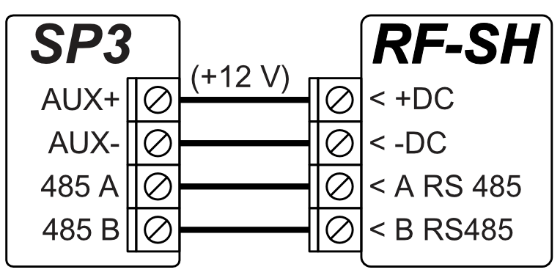
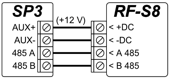
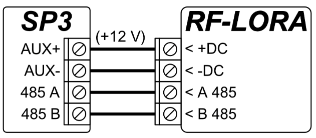
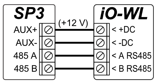
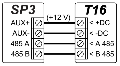
Most expanders and communication modules connect to the RS485 data bus. The module's power comes from the AUX+ (+12 V) and AUX− terminals, the data wires go to the 485 A and 485 B terminals, always A → A, B → B. Up to 8 devices can be connected to the bus, and the bus wire can be up to 100 m long. The exception is the RTX3 Paradox receiver, which connects to the keypad bus (GRN, YEL) (4.3). You set up the modules on the Modules page (6.5) and add the wireless devices on the Wireless page (6.6).
"Up to 100 m" is a theoretical maximum under ideal conditions – see the note in section 1.3.
Of the wireless receivers, each firmware version supports only its own; the full table of the versions and the supported modules is in section 1.7.
| Module | Wireless system | Required firmware (1.7) |
|---|---|---|
| RF-SH | Crow | SP3_xxx0, 1.01 or newer (SP3_xxx0_0101) |
| RTX3 | Paradox | SP3_xxx1, 1.12 or newer (SP3_xxx1_0112) |
| RF-HW | Honeywell | SP3_xxx2, 1.14 or newer (SP3_xxx2_0114) |
| RF-S8 | S8 | SP3_xxx4, 1.22 or newer (SP3_xxx4_0122) |
| RF-LORA | "Maximum" LoRa devices | for the MAXIMUM wireless devices SP3_xxx4, 1.21 or newer (SP3_xxx4_0121); for the LORA expanders any version |
| E485, T16, SF485, iO, iO-8, iO-WL, iO-MOD, LORA expanders | – | any version |
4.1 E485 Ethernet module
With the E485 module, the panel sends and receives event reports and control commands over wired internet. If an E485 is connected to the panel, the reports to the monitoring station and to Protegus 2 go over wired internet and mobile internet is not used; if the wired connection is interrupted, the panel switches to mobile internet, and when the wired connection is restored it switches back to it automatically. You set the priority of the channels (SIM, Wi-Fi, LAN – E485) on the Reporting to CMS page (6.3), and the E485 settings on the Modules page (6.5). With an E485, the panel does not need a SIM card.

- 1 LAN cable ("LAN cable")
The “up to … m” distances are theoretical maximums achievable under ideal conditions. In practice, the quality and routing of the cable, sources of interference and, for radio links, walls and terrain give a considerably shorter range. Plan with a margin, and on long runs check the connection during commissioning.
4.2 RF-SH wireless receiver (Crow)
With the RF-SH receiver, the panel handles Crow wireless devices: up to 32 detectors, 16 sirens, 42 remote controls and 8 wireless keypads. Required firmware: SP3_xxx0_0101 or newer (1.7).
4.3 RTX3 wireless receiver (Paradox)
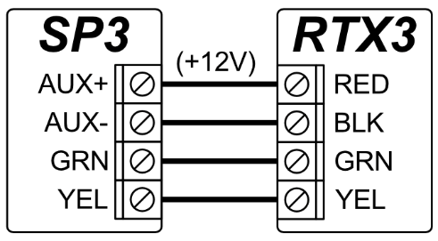
The RTX3 receiver connects not to the RS485 bus but to the keypad bus. With it, the panel handles Paradox wireless devices: opening detectors, motion detectors, the G550 glass break detector, the SD360 smoke detector, the REM2 and REM25 remote controls, the SR230 and SR250 sirens, the K37 keypad, the 2WPGM PGM and zone expander, and the RPT1 repeater. Required firmware: SP3_xxx1_0112 or newer (1.7). A separate article covers the RTX3 firmware, its wiring, and adding and deleting Paradox devices: FLEXi SP3 and the Paradox RTX3 wireless expansion module.
4.4 RF-HW wireless receiver (Honeywell)
With the RF-HW receiver, the panel handles Honeywell wireless detectors, sirens, keypads and remote controls. Required firmware: SP3_xxx2_0114 or newer (1.7).

4.5 RF-S8 wireless receiver
With the RF-S8 receiver, the panel handles S8 wireless detectors, sirens and remote controls. Required firmware: SP3_xxx4_0122 or newer (1.7). Registering the RF-S8, changing its firmware and pairing the S8 devices are described in a separate manual: RF-S8 transceiver and S8 detectors manual.
4.6 RF-LORA wireless receiver
With the RF-LORA receiver, the panel handles the "Maximum" LoRa wireless devices: up to 32 detectors, 16 sirens and 32 remote controls, as well as the LORA expanders (4.7). The MAXIMUM detectors, sirens and remote controls require SP3_xxx4 firmware, 1.21 or newer; the LORA expanders work with any firmware version (1.7). The receiver is set up on the Modules page (6.5), and the devices are added on the Wireless page (6.6).
4.7 LORA expanders
The LORA expanders (iO-LORA, iO8-LORA, PB-LORA, REL-LORA) connect to the panel by radio through the RF-LORA receiver, from up to 5000 m. iO-LORA: input and output expander with a CZ-Dallas iButton reader connection, powered from 12 V DC; a Wiegand reader connected to it does not work with the SP3. iO8-LORA: expander with eight inputs/outputs, powered from 12–26 V, with all of the panel's circuit types (3.2). PB-LORA: panic button. REL-LORA: relay module, powered from 100–230 V AC.
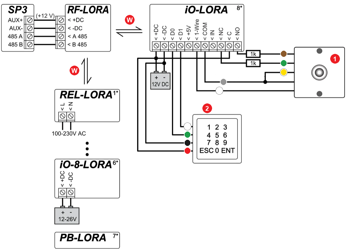
- 1 CZ-Dallas iButton reader ("CZ-Dallas reader")
- 2 entry reader: RFID reader with keypad, Wiegand 26/34 ("Entry reader", "RFID reader with keypad (Wiegand 26/34)") – does not work this way with the FLEXi SP3
- W wireless connection ("Wireless connection"), up to 5000 m ("up to 5000 m")
- brown wire, RED LED+ ("Brown wire", "RED LED+") – the red light
- green wire: on the CZ-Dallas reader Green LED+, the green light ("Green wire", "Green LED+"); on the entry reader D0 ("G - green wire (D0)")
- yellow wire, LED− ("Yellow wire", "LED-")
- grey wire ("Gray wire")
- white wire ("White wire"); on the entry reader D1 ("W - white wire (D1)")
- red wire, +U ("R - red wire (+U)")
- black wire, GND ("B - black wire (GND)")
The entry reader (2) connected to the iO-LORA in the drawing does not work with the FLEXi SP3. Connect the RFID reader directly to the panel (3.5).
The “up to … m” distances are theoretical maximums achievable under ideal conditions. In practice, the quality and routing of the cable, sources of interference and, for radio links, walls and terrain give a considerably shorter range. Plan with a margin, and on long runs check the connection during commissioning.
4.8 iO series expanders
If the panel needs more inputs (IN) or outputs (OUT), connect a wired or wireless Trikdis iO series expander (iO, iO-8, iO-WL, iO-MOD) to it. iO: input/output expander with a 1-Wire connection. iO-8: expander with eight inputs/outputs, with all of the panel's circuit types (3.2). iO-WL: wireless expander that connects to the panel through the iO-MOD transceiver, from up to 300 m; it can also be wired to the RS485 bus. The system can have up to 8 expansion modules and up to 4 iO-MOD units. The expanders are set up on the Modules page (6.5).

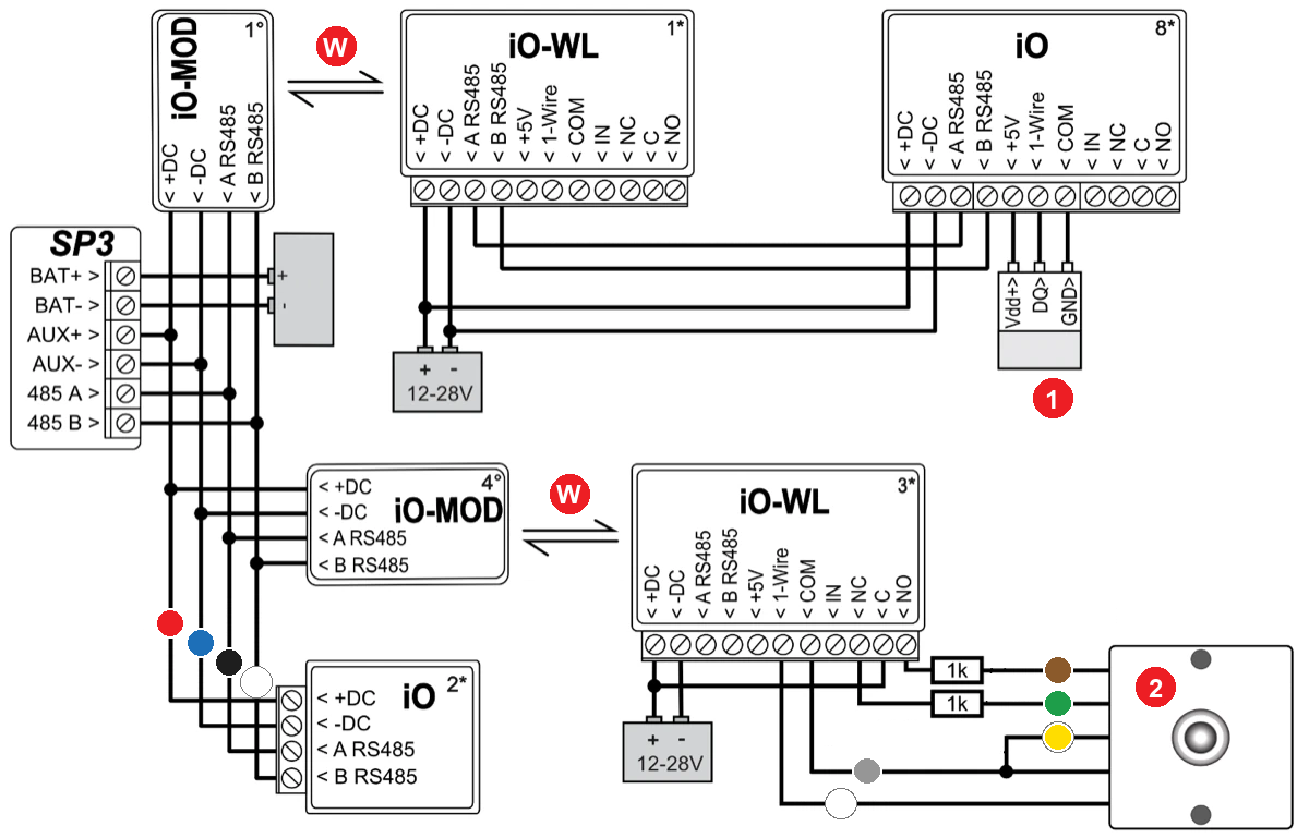
- 1 temperature sensor, DS18B20 or DS18S20 ("Temperature sensor: DS18B20 or DS18S20")
- 2 CZ-Dallas iButton reader ("CZ-Dallas reader")
- W wireless connection ("Wireless connection"), up to 300 m ("up to 300 m")
- red wire ("Red wire")
- blue wire ("Blue wire")
- black wire ("Black wire")
- white wire ("White wire")
- brown wire, RED LED+ ("Brown wire", "RED LED+") – the red light
- green wire, Green LED+ ("Green wire", "Green LED+") – the green light
- yellow wire, LED− ("Yellow wire", "LED-")
- grey wire ("Gray wire")
The “up to … m” distances are theoretical maximums achievable under ideal conditions. In practice, the quality and routing of the cable, sources of interference and, for radio links, walls and terrain give a considerably shorter range. Plan with a margin, and on long runs check the connection during commissioning.
4.9 T16 radio transmitter
The T16 VHF/UHF radio transmitter forwards the panel's events to the monitoring station over the Trikdis radio network: it sends both its own events and those received from the panel, and the monitoring station can forward them to the user.
4.10 SF485 Sigfox module
The SF485 is a backup channel: if the primary channel fails, it sends the panel's events over the Sigfox network to the monitoring station or to the Protegus 2 app, in Contact ID format.

4.11 Measuring DC voltage
The panel can measure DC voltage of 0–30 V; above 30 V the board is damaged. The positive pole of the measured voltage goes to IO1 (IN1 on the factory drawing), the negative to the C terminal.
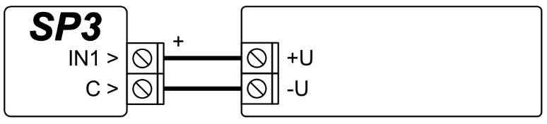
Connect the panel to the computer with a USB cable and start TrikdisConfig (chapter 6); the program automatically recognises the connected panel and opens its settings window. On the Sensors page, add the In1 Voltage sensor and the limits:
- Max – above this voltage an event is generated if the High box is ticked;
- Min – below this voltage an event is generated if the Low box is ticked.

The measured voltage can also control a PGM output. On the Outputs tab of the PGM page set the output to Remote Control mode, then on the Set Action tab enter the condition:
- Enable – enabling the PGM;
- PGM No. – the controlled PGM output;
- Action – the output's operation: PGM OFF (switches off), PGM ON (switches on), Pulse OFF (on the command switches off for the pulse time, then switches back on), Pulse ON (switches on for the pulse time, then switches off);
- Pulse time, s – the length of the pulse, 0–9999 s;
- Factor – the source of the condition: Sensor;
- Factor No. – the voltage measuring input (S1);
- Start when – the condition: Higher than set (above the set value) or Lower than set (below it);
- Set value – the monitored voltage (V).


5. Protegus 2 and remote control
You can control the "FLEXi" SP3 remotely in three ways: from the Protegus 2 app, by SMS and by phone call. The app works on every version that can reach the internet (WiFi, Ethernet or mobile network). SMS commands and call control are only available on the versions with a mobile network modem (for example SP3_24E, SP3_44E, SP3_12E) and only with a working SIM card. The SP3_3E (WiFi + Ethernet) version has no modem.
5.1 Connecting to the Protegus 2 account
In Protegus 2 the user arms and disarms the system, sees the status of the zones and partitions, and receives notifications of events. Before adding the panel to the account, check the following:
- Supply voltage – the POWER LED is steady green.
- Network – the NET LED is steady green (mobile network) and/or the MOD LED is steady green (WiFi or Ethernet module). The meaning of the LEDs is described in section 1.6.
- SIM card – on a modem version the SIM is active, and you have entered the PIN code in TrikdisConfig (System Options → SIM → PIN), or you have switched off the PIN request on the card.
- Cloud service – on the Users & Reporting → Protegus tab of TrikdisConfig, Enable cloud service is ticked (6.4). The factory value of the Cloud access code is 123456; if you change it, the app asks for the new code when the system is added.
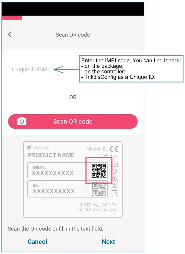
- Unique identifier – you will find the panel's IMEI/Unique ID number on the sticker on the packaging and on the board, and it is also shown in the lower left corner of TrikdisConfig once you have read the panel.
If you do not yet have a Protegus account, create one with the Sign up link at www.protegus.app and activate it by clicking the link received in the e-mail; then install the Protegus 2 app on your phone and log in with your username and password.
Creating the system in the Protegus 2 application
- Download the Protegus 2 application to your phone or open it in a browser
- Register an account if you haven't already.
- Log into your account.
- On the main page, click the "+" button to create a system
- Enter the unique identifier of the TRIKDIS device (you can also scan the barcode or QR code with your phone's camera), which you can find
- On the sticker of the device
- On the device's cardboard box
- In the bottom left corner of TrikdisConfig (selectable and copyable format)
- Enter the system name and select a time zone
- Your system is created, you can still name the partitions and zones at the next step, but you can do this later anytime.
- In the last step, your system's home screen will appear. Wait until the yellow stripe disappears and your system is ready.


Further users
The owner can invite further users in Protegus 2. The system also sends an invitation to the addresses written in the Email column on the Users & Reporting → Users tab of TrikdisConfig, so the user sees the system from their own account (6.4).
5.2 Arming and disarming in the app
- Open the system in the Protegus 2 app. On the home screen every partition has its own card and padlock: a closed, red padlock means an armed partition, an open, green padlock a disarmed one.
- Tap the partition's padlock and select the required action: arm or disarm.
- If the app asks for it, enter the PIN code.
The padlock takes on the actual state in response to the event received from the alarm panel; the app also confirms in the event list and in a notification whether the panel has carried out the action.
With the SP3, after tapping the padlock you have to enter the panel's user code. This is the code in the Code column on the Users & Reporting → Users tab of TrikdisConfig, not the password of the Protegus 2 account. Each partition appears on a separate card, and you only see the partitions to which the user has rights in the Areas column. Besides full arming, you also start the partial modes from the app: Stay (you stay at home, the interior zones are not armed) and Sleep (night mode). Which mode a zone monitors in is decided by the zone's Definition field (6.7).

If the app does not follow the panel
If nothing happens in response to commands, or the app shows something completely different from the panel's real state, open the Settings → System configuration menu in Protegus 2 and press the Sync button in the System out of sync? row. The app reads the panel's settings again.
5.3 Configuration and control by SMS
Only on the modem versions. You send the SMS to the number of the panel's SIM card. Every message has the same structure:
Command space Password space Data
The password is the six-digit SMS password (System Options → Access, 6.2). Its factory value is 123456. For security reasons, change it during commissioning to a password known only to you, in TrikdisConfig or with the PSW command – and do not forget it – and do not give out the number of the panel's SIM card unnecessarily. The data field depends on the command; for several commands it is empty.
Who can send commands?
The administrator can control the panel both by SMS and by call. If you want to authorise another user as well, add their phone number on the Users & Reporting → Users tab of TrikdisConfig (6.4) or with the SETN command. The panel sends its replies with the texts set on the SMS answer texts tab.
| Command | Data | What it does | Example |
|---|---|---|---|
| INFO | – | Status query: object name, partition states, IMEI, signal strength, firmware version, serial number. | INFO 123456 |
| RESET | – | Restarts the panel. | RESET 123456 |
| OUTPUTx | ON | Switches output x on. | OUTPUT1 123456 ON |
| OFF | Switches output x off. | OUTPUT1 123456 OFF |
|
| PULSE=ttt | Switches output x on for ttt seconds (three digits). | OUTPUT1 123456 PULSE=002 |
|
| PSW | new password | Changes the SMS password. | PSW 123456 654123 |
| TIME | YYYY/MM/DD,hh:mm:ss | Sets the date and time. | TIME 123456 2026/10/30,10:02:00 |
| TXTA | object name | Sets the object name (this appears in the reports). | TXTA 123456 Home |
| RDR | phone number#text | The panel forwards the text after the # by SMS to the specified number. The number starts with a + sign and the country code. | RDR 123456 +36301234567#forwarded text |
| ASKI | – | State of the inputs (IN) by SMS. | ASKI 123456 |
| ASKO | – | State of the outputs (OUT) by SMS. | ASKO 123456 |
| ASKA | – | State of the partitions by SMS. | ASKA 123456 |
| ASKT | – | Values of all temperature sensors by SMS. | ASKT 123456 |
| ARM | SYS:x | Arms partition x (1–8). | ARM 123456 SYS:1 |
| DISARM | SYS:x | Disarms partition x (1–8). | DISARM 123456 SYS:1 |
| STAY | SYS:x | Arms partition x in Stay mode (1–8). | STAY 123456 SYS:1 |
| SLEEP | SYS:x | Arms partition x in Sleep mode (1–8). | SLEEP 123456 SYS:1 |
| FRS | – | Resets the power of the fire detectors, if an output is defined as Fire Sensor Reset. | FRS 123456 |
| SETN | PhoneX=number#name#e-mail | Adds a user in row x with phone number, name and e-mail address; the phone number and the name are separated by a # sign. The number starts with a + sign and the country code. | SETN 123456 PHONE5=+36301234567#JOHN#john@example.com |
| PhoneX=DEL | Deletes the phone number and name in row x. | SETN 123456 PHONE5=DEL |
|
| UUSD | *code# | Sends a USSD code to the mobile operator (for example a balance query). The command name appears in the panel exactly like this, as UUSD. | UUSD 123456 *245# |
| CONNECT | Protegus=ON | Connects to the Protegus cloud. | CONNECT 123456 PROTEGUS=ON |
| Protegus=OFF | Disconnects from Protegus. | CONNECT 123456 PROTEGUS=OFF |
|
| Code=123456 | The access code of the Protegus cloud (Cloud access code). | CONNECT 123456 CODE=123456 |
|
| IP=address:port | IP address and port of the main monitoring channel. | CONNECT 123456 IP=0.0.0.0:8000 |
|
| IP=0 | Disables the main channel. | CONNECT 123456 IP=0 |
|
| ENC=123456 | TRK encryption key. | CONNECT 123456 ENC=123456 |
|
| APN=name | The APN name of the SIM card. | CONNECT 123456 APN=INTERNET |
|
| USER=name | APN user name. | CONNECT 123456 USER=User |
|
| PSW=password | APN password. | CONNECT 123456 PSW=Password |
First check
The INFO command is the quickest way to see on site that the SIM is live, the panel accepts commands, and what the signal strength is. The reply arrives within a few seconds.
5.4 Control by phone call
Not on every version
Call control does not work on SP3_xx7x panels. The SP3_12xx type with firmware 1.14 or newer does not speak voice messages, but the keypad commands still work.
Conditions:
- The caller's phone number is on the Users & Reporting → Users tab, and the PGM column is ticked for the user (output control from a phone), or the system is divided into at least one partition and the user has rights to it.
- The Output definition field of the output to be controlled is Remote control (6.8). For pulse control, Pulse time is also filled in.
Call the number of the panel's SIM card. The panel answers the call; then dial the command on the phone's keypad:
| Keys | Function | Example |
|---|---|---|
| [1][partition][#] | Arms the specified partition. | 12# – arms partition 2 |
| [2][partition][#] | Disarms the specified partition. | 22# – disarms partition 2 |
| [3][output][#][state] | Controls the specified output. State: 0 – off, 1 – on, 2 – off for the pulse time, 3 – on for the pulse time. | 31#1 – switches output 1 on; 32#3 – switches output 2 on for the pulse time |
Only on the old SP3_12xx panels (firmware up to 1.13), for voice messages:
| Keys | Function | Example |
|---|---|---|
| [4][#][recording number][#] | Start recording a voice message (1–5). | 4#1# |
| [5] | Play back the message just recorded. | 5 |
| [6] | Save the recording. | 6 |
Recording voice messages
The start and end of the recording are signalled by a beep. A message is at most 15 seconds long. The end of playback is also signalled by a beep, and only start the next operation after the beep. The panel plays the recorded message to the called user in the event of an alarm: which message belongs to which zone is set in the zone's Sound field (6.7). Voice calls are only available on the SP3_12xx version, with firmware up to 1.13.
6. TrikdisConfig – the settings in detail
TrikdisConfig is Trikdis's free configuration program running on Windows. With it you read and write every setting of the panel: locally over USB, or remotely through the Protegus cloud. You download the program from trikdis.com (type TrikdisConfig into the search field).
All Trikdis devices can be programmed using a common software. The software is called TrikdisConfig and can be downloaded from the manufacturer's website.
After downloading, install the program. If a new version is available each time you start TrikdisConfig, download and install the recommended update!
Connecting over USB
- Install and start TrikdisConfig.
- Connect the panel to the computer with a USB Mini-B cable. The program recognises the panel and opens the SP3 settings window.
- Press the Read [F4] button. If the program asks for a code, enter the administrator or installer code (6.2.6). With the factory administrator code it does not ask.
- Set what you need, then press the Write [F5] button. Only this writes the settings into the panel.
Programming mode
If you plug the USB cable into a working panel that is under power, the panel switches to programming mode and performs no alarm function until the cable is unplugged. With a system in operation, tell the user, and unplug the cable at the end.
The buttons in the top row: Read [F4] – read from the panel; Write [F5] – write to the panel; Open [F8] – open settings previously saved to a file; Save [F9] – save the current settings to a file; Disconnect – end the connection. The windows of the left-hand menu: System Options, Reporting to CMS, Users & Reporting, Modules, Wireless sensors, Zones, PGM, Sensors, System events, Events Log and Firmware (updating the firmware, chapter 9). In the lower left corner you see the Remember password and Show passwords checkboxes, the Default settings → Restore button (6.12) and the panel's IMEI/Unique ID number.
Save it to a file
The file saved with the Save [F9] button is the system's documentation. After a board replacement or a factory reset, you can load the whole lot back in minutes with Open [F8] and then Write [F5].
You can also configure the panel remotely: on the TrikdisConfig start screen, type the panel's IMEI/Unique ID number into the Remote access field and press the Configure button (figure in section 6.6.2, the full procedure in chapter 7). This requires the cloud service to be switched on (6.4.3) and a working network connection.
6.1 The status bar
With a panel connected, the bottom line of the program and the lower left field show the device's data.
| Field | Meaning |
|---|---|
| IMEI/Unique ID | The panel's unique identifier. On a modem version the IMEI, on a WiFi/Ethernet version a hardware identifier. Protegus 2 and Remote access ask for this. |
| Status | The status of the operation (for example "reading done"). |
| Device | The panel's type, in the form SP3_xxxx. |
| SN | The panel's serial number. |
| BL | The bootloader version. |
| FW | The firmware version. |
| HW | The hardware version. |
| State | The connection mode: USB or remote. |
| Role | The access level after entering the code: Administrator or Installer. |

The Read [F4] button reads and displays the settings stored in the panel. Below we go through the fields window by window.
6.2 System Options
It consists of six tabs: System general, Partitions, Scheduler, Holidays, System troubles and Access.
6.2.1 System general tab
General group:
- Object ID – object identifier, a four-digit hexadecimal number (0–9, A–F). It is assigned by the monitoring station (CMS); it is only needed if the panel reports to a monitoring station. FFFE and FFFF cannot be used.
- Object name – the name of the object, up to 20 letters and digits. It appears in the SMS reports.
- Test period – if ticked, the panel sends a test report at this interval, unless Start test at is also ticked and you have entered a time.
- Start test at – the daily time of the test report.
- Areas in test SMS – the test SMS also contains the status of the specified partitions.
- Clear Events after reset – on restart, events not yet sent are deleted from the buffer.
- Text language – the SMS messages use the characters specific to the selected language.
- Suspend event reporting when … same events per … s – suspending reporting if the same event repeats more than the specified number of times within the specified time (for example a faulty detector). Restore event reporting after – after this many minutes (0–999) the panel reports the event again.
- Call – on an event the panel calls the user this many times. If the call is answered or rejected, it does not call again. A call lasts 20 seconds.
- EOL Type – the value of the end-of-line resistors connected to the zones: RT is the tamper resistor, R1 that of detector 1, R2 that of detector 2. The wiring is shown in chapter 3.
- Communication path test – at this interval the panel also sends a test message to the monitoring station over the backup channels, then returns to the main channel.
- LED out as 2Wire fire – tick if you connect a two-wire fire detector to the LED output.
SIM group:
- PIN – the SIM card's PIN code. If the card has no PIN request, leave the factory value.
- APN – the name of the mobile operator's internet access point. Mandatory if the panel reports to the Protegus cloud or the monitoring station over mobile internet.
- Login, Password – APN username and password, only if the operator requires them.
- Locked ICCID – the SIM card's ICCID number. If you fill it in, the panel only works with this card.
- Preferred operator – operator code (MCC + MNC). If you fill it in, the panel only registers on this operator's network.
Operator codes – example: Hungary
Yettel 21601, Telekom 21630, One (formerly Vodafone) 21670. Your own operator's code consists of the country's MCC and the operator's MNC in the same way. If left empty, the panel selects the network automatically; only enter the code if it has to stay on a particular network.
Time settings group:
- Set PC time – writes the computer's time into the panel. If Time synchronization is set to Disabled, this time stays; if modem or server, the panel synchronises from there after power-up.
- Time zone (Hours) – the time zone; for example +1 in Central Europe (e.g. Hungary).
- Time set – the time server the panel synchronises with on power-up.
- Daylight saving time – automatic switching between summer and winter time.
- AC failure delay – the panel reports a mains power failure with this delay, and the restoration also with a delay.

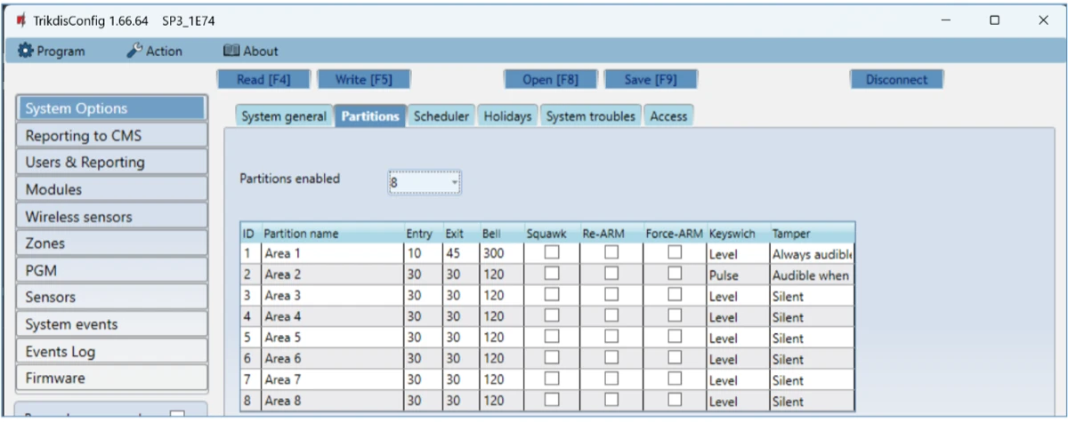
6.2.2 Partitions tab
- Partitions enabled – how many independent parts (partitions) you divide the system into.
- Partition name – the name of the partition.
- Entry – entry delay, 0–999 s. This is how much time you have to go through the Delay zone to the keypad and disarm the system.
- Exit – exit delay, 0–999 s. After arming – counted from the arming code entered on the keypad – this is how much time you have to leave the premises through the Delay zone. With remote arming (for example from Protegus 2) the system arms immediately, without exit time.
- Bell – the siren's operating time in the event of an alarm, 0–999 s.
- Squawk – the siren chirps once on arming and twice on disarming.
- Re-ARM – automatic re-arming if the system was disarmed remotely, but nobody violated the Delay zone during the entry time.
- Force-ARM – forced arming. The system can be armed even if Stay zones are open, as long as the entry zone is closed.
- Keyswitch – the keyswitch zone arms and disarms with a pulse (Pulse) or a level (Level).
- Tamper – handling of the tamper event when the panel detects detector tampering: Silent (only a report goes to the recipients, the siren does not sound), Audible when armed (the report goes, the siren only sounds if the tampering happens with the system armed), Always Audible (the report goes, and the siren sounds even with the system disarmed).
6.2.3 Scheduler tab
Automatic arming and disarming according to the days of the week, with holidays.
- Enable – enabling the schedule.
- Partition – which partition it applies to.
- Time – the time of the action.
- Not Armed – the action only runs if the panel is not armed in full (Away) mode.
- Action – the mode to set: Disarm, Arm, Sleep or Stay.
- Monday … Sunday – on which days it is valid.
- Holiday – behaviour on a holiday: Disabled (no holiday), Ignore on holidays (does not run on holidays), Additional when holidays (also runs on holidays), Only holidays (runs only on holidays).
- Holiday group – which holiday group (Any, 1–4) to treat as a holiday. With Any, any active holiday counts.

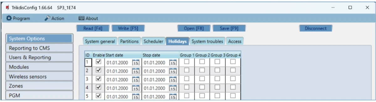
6.2.4 Holidays tab
- Enable – enabling the holiday.
- Start date, Stop date – the first and last day of the holiday. For a one-day holiday the two are the same.
- Group 1 … Group 4 – you arrange the holidays into groups; the scheduler refers to these.
6.2.5 System troubles tab
If you tick an internal fault here, the system cannot be armed while that fault is present. This way you can make sure that, for example, nobody arms it with a flat battery or without mains power.

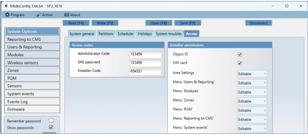
6.2.6 Access tab
Access codes group:
- Administrator Code – factory value 123456. Full access to the settings. Six characters, Latin letters and/or digits.
- SMS password – factory value 123456. The password of the SMS commands (5.3), with which the system can be controlled securely by SMS; for security reasons replace it with a six-digit password known only to you.
- Installer Code – factory value 654321. The installer's access to the settings; for security reasons replace it with a six-digit code known only to you.
Installer permissions group – here you specify what someone logging in with the installer code may change.
Factory administrator code
As long as the administrator code is the factory 123456, after Read [F4] the program shows the settings without asking for a code.
Before handover
Change all three codes before handover. The administrator code belongs to the owner; the owner can also change the installer code and its permissions later.
6.3 Reporting to CMS
The panel sends events to the monitoring station (CMS) over mobile internet (IP) or by SMS. You can set several channels: the main (Primary) and the parallel (Parallel) channel work at the same time, so two receivers can get the events; a backup (Backup) channel can be assigned to each, which takes over if the connection of the main or parallel channel is interrupted. The connection is encrypted and password-protected; a Trikdis receiver is needed to receive it: over IP the IPcom software receiver, the RL14 or the RM14 hardware receiver; for SMS the RL14, the RM14 or the GM14. SMS is good as a backup channel because it works without mobile internet, but it is not recommended as the main channel.
6.3.1 Reporting tab
Primary channel, Backup channel, Parallel channel and Parallel backup channel groups:
- Communication type – the protocol used with the receiver: TCP/IP, UDP/IP, SMS or Disabled.
- Domain or IP – the receiver's domain name or IP address.
- Port – the receiver's port.
- Protocol – TRK for a Trikdis receiver, SIA DC-09 for an IP receiver that accepts the SIA DC-09 format.
- Phone number – only for SMS: the phone number of the Trikdis SMS receiver, with the international country code (for example 36… for Hungary).
- Encryption key – six-digit encryption key; it must match the receiver's key.
If you also fill in the parallel channel, the events go over both channels at the same time, so two receivers (for example a local and a central monitoring station) get them at the same time. The two channels must not point to the same receiver.
Backup channel 2 and Parallel backup channel 2 – SMS backup: the number of the monitoring station's SMS receiver goes in the Phone number field (with the country code). The panel sends here if sending fails on the main, the parallel and the backup channel; this is especially useful because it also works when there is no IP connection in the mobile operator's network. It only works if the first channel and its backup are IP. An SMS is sent on first power-up, and when the IP connection on the first channel and its backup is interrupted.

6.3.2 Settings tab
Settings group:
- Return to primary after – after this many minutes the panel tries to return to the main channel.
- IP Ping period – the interval of the IP connection's check signals in seconds; the tick switches it on.
- SMS Ping period – the interval of the SMS channel's check signals in minutes; the tick switches it on.
- Backup reporting after – after this many unsuccessful sends the panel switches to the backup channel.
- DNS1, DNS2 – addresses of the DNS servers. With any IP setting, enter a DNS address that the provider supports.
- Object ID in SIA DC-09, SIA DC-09 receiver No., Line No. – object number, receiver number and line number for the SIA DC-09 protocol.
- Local time in SIA – the messages sent to the monitoring station contain the panel's own time.
Reporting mode group – which path the panel should use to communicate with the monitoring station and Protegus 2. The order of the types matters: if the Main type connection cannot be established, the panel switches to the Backup type, then the Backup type 2 path.
- Main type, Backup type, Backup type 2 – SIM, WiFi or LAN(E485), separately in the CMS and Protegus columns.
- Radio T16 (SF485) – tick if a T16 radio transmitter also sends. The T16 works as a backup channel if at least one of SIM, WiFi or LAN is in use; if there is no other connection, the T16 is the main channel. The T16 only sends reports to the monitoring station.
- Return to main (both channel) – after this many minutes the panel tries to return to the main path if it was sending over a backup.
Communicator network settings group (WiFi version):
- DHCP mode – when ticked, the panel automatically gets an IP address, subnet mask and gateway.
- Static IP, Subnet mask, Default gateway – for manual setup.
- WiFi SSID name, WiFi SSID password – the name and password of the WiFi network.
SIM parameters group:
- Disable indication of the absence of a SIM card – the panel does not indicate that there is no SIM card.
- Use dial and SMS when working over internet module – when ticked, calls and SMS also work when the panel reports over WiFi or LAN. Without the tick, if there is WiFi, the panel does not use SMS and calls; if there is no WiFi without the tick, the panel can still be controlled by call and SMS, and sends SMS to the user.
- Disable the use of SIM card mobile data – the panel does not use the SIM's mobile data, it only sends over WiFi. If the WiFi drops out temporarily, it stores the events and sends them later.

6.4 Users & Reporting
In the rows of the Users tab (Users & Reporting to User group) you add the users:
- Name – the user's name; it appears in the event SMS messages.
- Tel number – phone number with the international country code. From this number the user can control the system, and receives the SMS messages on it. The first eight numbers receive reports by SMS and call.
- Email – e-mail address; the user receives an invitation to Protegus 2.
- Code – the user's arming and disarming code.
- Tag code – the identification number of an RFID card, key fob or iButton key.
- Areas – which partitions the user may operate.
- A, D – may arm and disarm respectively.
- PGM – may switch the outputs by phone call, with DTMF signals (5.4).
- ACK – the panel confirms by SMS the execution of the commands received.
- FWD – the panel forwards SMS messages arriving from non-users (balance information, advertising) to this user.
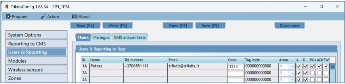
6.4.1 RFID cards and key fobs
You do not enrol an RFID card or key fob by touching it to the reader: you type the card's identification number manually as a decimal number into the Tag code field, then Write [F5]. The number is printed on most cards.
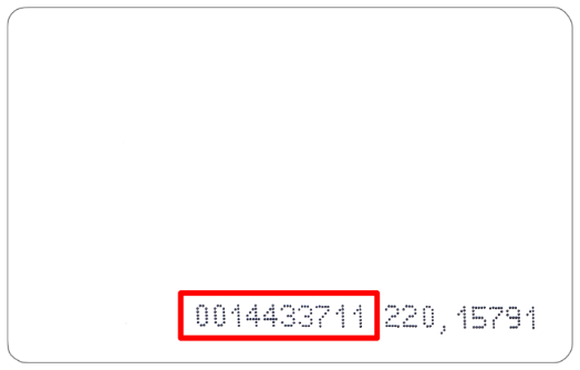
One Wiegand reader without a keypad, for door opening
- Connect the reader's data wires to the board's GRN and YEL terminals.
- On the Modules → Keypads tab, in the Keypad parameters group, set Keypad type to Wiegand reader, even if there is no keypad.
- In the PGM window, set the Output definition field of the controlled output to Remote control, and Pulse time, s to, for example, 5.
- On the PGM → Control tab, in the reader's row tick the En box, enter the output's number in the PGM field, and set PGM mode to Pulse.
6.4.2 iButton keys
Enrolling with a TM17 reader:
- If the Tag code list is empty, the first key enrolled goes into the first row of the list and becomes the master key (Master).
- To switch on enrolment mode, hold the master key to the reader's "eye" for at least 10 seconds. In enrolment mode the TM17's State LED flashes green.
- Touch the user keys to the reader one by one. Three beeps signal that the key has been added to the system.
- At the end, touch the master key to the reader again; the State LED stops flashing.
- To delete all keys (including the master key), hold the master key to the reader for at least 20 seconds.
With a CZ-Dallas reader the same way, just without LED indication: master key for 10 seconds, user keys one by one, at the end the master key again; deletion with 20 seconds.
The role of the master key
The master key is for enrolling the other keys. If you also use it for arming and disarming, the command is executed with a delay.
6.4.3 Protegus tab
Cloud application group:
- Enable cloud service – enabling the Protegus cloud. Through it the panel communicates with Protegus 2, and through it the panel can be configured remotely with TrikdisConfig.
- Parallel reporting – the events go at the same time over the main channel to the monitoring station and to Protegus 2.
- Cloud access code – six-digit code for the Protegus 2 connection, factory value 123456.
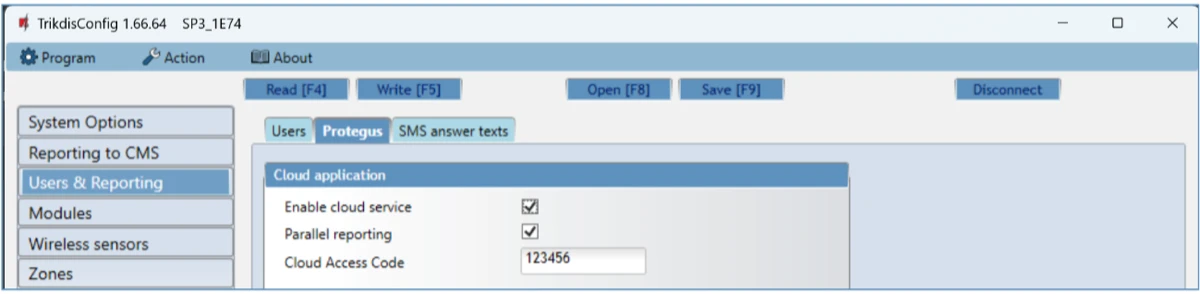
6.4.4 SMS answer texts tab
You can rewrite the text of the replies to SMS commands in the SMS text column, for example into your own language.
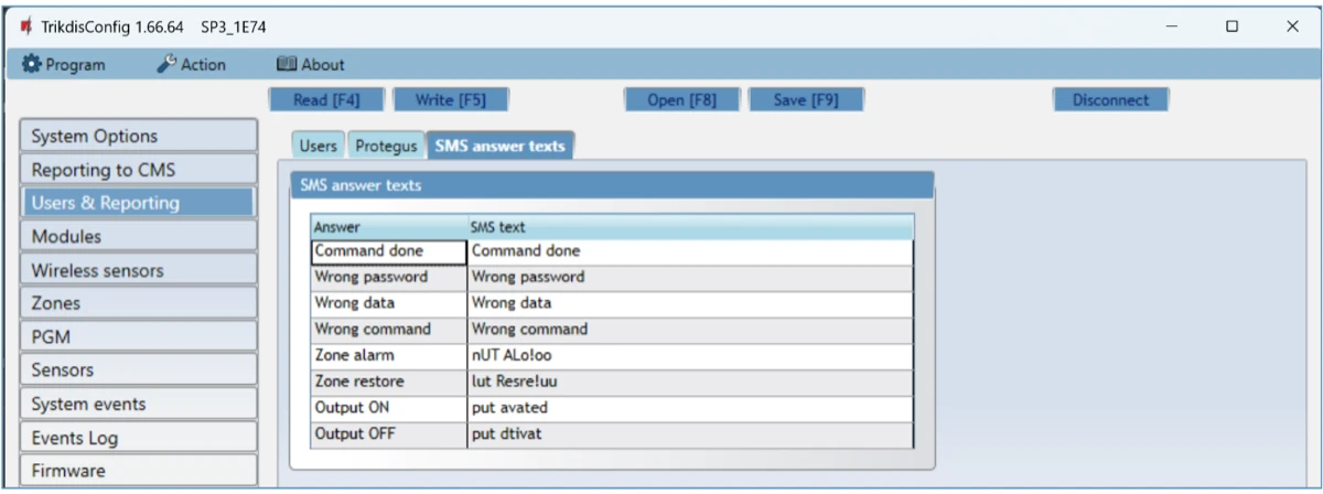
6.5 Modules
Keypads tab:
- Serial – the keypad's serial number, recognised automatically by the panel. To delete, write zeros, or press the Remove button.
- Keypad type – the keypad's type, recognised automatically.
- Areas – which partitions the keypad may operate (only for FLEXi SK LCD, FLEXi SK LED, SK LCD Button and SK LED Button keypads).
- Remove – deleting the keypad from the list.
Keypad parameters group:
- Keypad type – the type of keypad connected to the GRN and YEL terminals: Crow CR16, Paradox LED or Wiegand reader.
- Additional Wiegand on 1IO/2IO – tick if you connect a second RFID reader to the IO1 and IO2 terminals. These then cannot be used as inputs or outputs.
- 6 digits user code – six-digit user code on the keypad. To an existing four-digit code the program appends the first two digits (1234 becomes 123412); every four-digit user code is converted this way.
- Duress code type – the type of duress code. Under duress you arm or disarm with it: the system executes it and silently sends an alarm to the monitoring station.
- Quick ARM – the keypad's ARM, STAY and SLEEP buttons arm without a code.
- Incorrect codes until lockout – after this many wrong codes the keypad locks.
- Lockout timer – the lockout time in minutes.
- Panic alarm type, Medical alarm type, Fire alarm type – the effect of the keypad's panic, medical and fire function buttons when pressed: Audible (the siren sounds, the keypad gives an audible alarm, and a report goes to Protegus 2 and the monitoring station), Silent (only a report goes to Protegus 2 and the monitoring station, the panel switches off the audible alarm), Disabled (no report goes either to Protegus 2 or to the monitoring station).
- Low voltage reader (1IO/2IO) – if the connected RFID reader does not work, use this to switch the protocol between the panel and the reader.
- Use fingerprint – for a fingerprint reader with the Wiegand 26/34 protocol.
- Do not change charset – on the SK-LCD TouchPad keypad, the character encoding of the zone and partition names stays unchanged.
- Custom entry beep – the sound of the entry delay on the keypad is intermittent.
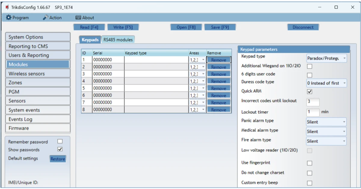
RS485 modules tab:
- ID – the module's number.
- Module – the expander's type from the list: iO, iO-WL, TM17, iO-8, RF-SH, E485, T16, SF485, iO-MO, iO-LORA, iO8-LORA, PB-LORA, REL-LORA, RF-LORA, RF-HW, RF-S8.
- Serial No. – mandatory, a six-digit number from the sticker on the module's housing and packaging.
- Area – the module's partition. The TM17 shows the status and zones of this partition.
- Name – the module's name.
- Firmware version – as soon as the panel finds the module, its firmware version appears here. This is the sign that the module is alive.

E485 settings tab – the network settings of the E485 LAN communicator: DHCP mode (automatic address: when ticked, the panel automatically reads the network settings – subnet mask, gateway – and automatically gets an IP address), or for manual setup Static IP, Subnet mask, Default gateway.

6.6 Wireless sensors
With the RF-LORA module, the "FLEXi" SP3 uses the wireless detectors, sirens and remote controls of the manufacturer Maximum. This requires firmware with receiver code 4 on the panel, at least version 1.21 (SP3_xxx4_0121 or newer; the 4th digit of the firmware name is the receiver type, see 1.7). Connect the RF-LORA transceiver to the panel's RS485 bus (4.6). First you register the RF-LORA module with the panel (6.6.1), then you enrol the detectors: remotely from TrikdisConfig (6.6.2) or with the module's LEARN button (6.6.3). Pairing the S8 detectors working with the RF-S8 receiver is described in chapter 4 of the RF-S8 transceiver and S8 detectors manual.
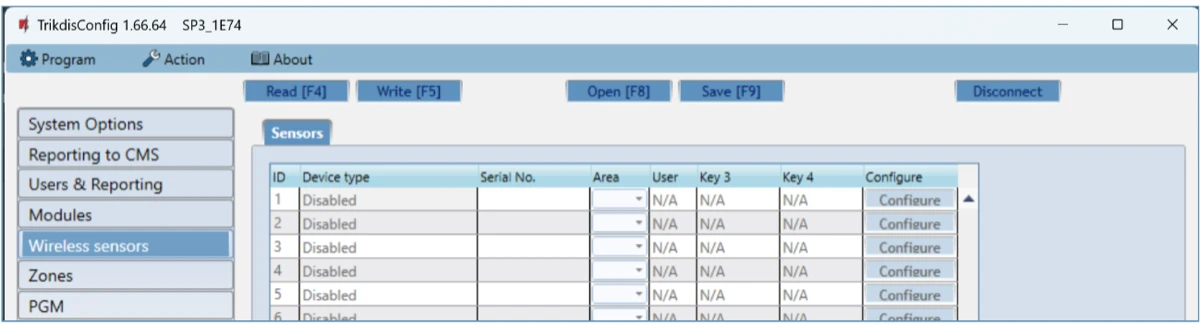
6.6.1 Registering the RF-LORA
- Switch on the panel's power supply and wait 1 minute.
- Start TrikdisConfig and connect the panel to the computer with a USB Mini-B cable.
- Press the Read [F4] button and open the Modules → RS485 modules tab. If RF-LORA transceiver is in the list with its serial number and firmware version, you are done and the remaining steps are skipped.
- If it is not there, select RF-LORA transceiver in the Module field of an empty row.
- Type the module's serial number from the sticker on its housing or packaging into the Serial No. field.
- Write [F5], then unplug the USB cable.
- Wait 1 minute while the panel and the RF-LORA connect.
- Plug the USB cable back in and press the Read [F4] button. The RF-LORA's firmware version appears in the Modules window: the module is registered.
- Unplug the USB cable, press the Disconnect button and wait 1 minute.
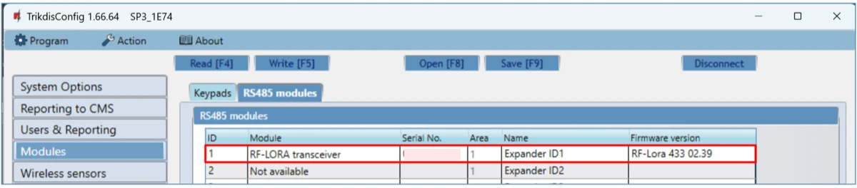

6.6.2 Pairing detectors remotely
Conditions for remote configuration: an activated SIM card with the PIN entered or switched off and with mobile internet (or a WiFi connection), the cloud service switched on (6.4.3), power and a network connection (the NET LED steady green).
- On the TrikdisConfig start screen, type the panel's IMEI/Unique ID number (on the sticker on the board and the packaging) into the Unique ID field of the Remote access group, and press the Configure button.
- In the window that opens, Read [F4]; if needed, enter the administrator or installer code.
- Open the Wireless sensors window and press the Learn sensors button. The RF-LORA switches to learning mode, its DATA/TROUBLE LED starts flashing green-red, and TrikdisConfig opens the learning window.
- Put the batteries into the detectors (motion, opening, water, smoke detector, siren). You can enrol several detectors at once. The RF-LORA should be at least 1 m away from the detectors.
- Press the detector's TAMPER button. The RF-LORA's DATA/TROUBLE LED briefly flashes green (the detector has been added), then after a few seconds green-red again.
- TrikdisConfig opens a new window: enter the detector's Zone number and Zone definition, then Save. The detector is added to the list.
- For the next detector, the TAMPER button again, and so on. At the end, press the Stop learning button.
- Answer Yes to the question: the detectors are written into the panel (No if you still want to adjust them first). Wait a few minutes, then Read [F4]: the enrolled detectors are shown in the Wireless sensors window, with their serial numbers in the Serial No. column.
- Check in the Zones window that the detectors have been assigned to the correct zone and partition. If the zone's Type field is EOL_T, the detector's tamper monitoring is also active. After making changes, Write [F5].
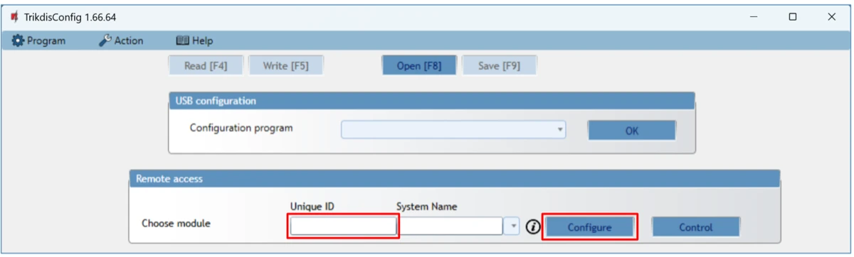


- T tamper button ("Tamper")
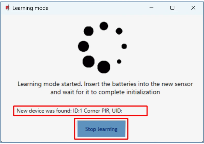
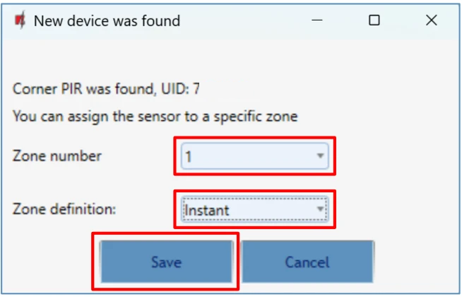


Deleting a wireless detector
Connect to the panel over USB or remotely, Read [F4], then in the Device type column of the Wireless sensors window select Disabled for the detector to be deleted, and Write [F5].
6.6.3 Pairing with the LEARN button
- The RF-LORA must be registered with the panel (6.6.1), and the panel must be switched on.
- Remove the RF-LORA's cover. Press and hold the LEARN button until the DATA/TROUBLE LED starts flashing green-red, then release it. The flashing indicates learning mode.
- Put the batteries into the detectors and press the detector's TAMPER button. A short green flash of the DATA/TROUBLE LED indicates success; after a few seconds it flashes green-red again. For the next detector, the TAMPER button again.
- At the end, press and hold the LEARN button until the green-red flashing stops, then release it. The RF-LORA has left learning mode.
- Connect the panel to the computer over USB, start TrikdisConfig, Read [F4]. In the Wireless sensors window the enrolled devices are shown with their seven-digit serial numbers.
- Check the zones and partitions in the Zones window; after making changes, Write [F5].
6.6.4 RF-SH and Crow devices
Older systems with the RF-SH module use the wireless devices of the Crow FW2 and Shepherd (SH) series. The RF-SH is no longer available; the description has been kept here briefly for maintaining existing systems; the module's wiring is shown in section 4.2.
- Registering the RF-SH – as with the RF-LORA (6.6.1): on the Modules → RS485 modules tab RF-SH, Serial No., Write [F5], USB out, wait 1 minute, USB back in, Read [F4]; the appearance of the firmware version is the sign of success.
- FW2 detectors – press the module's LEARN button until the LEARN LED flashes green. Insert the detector's battery and wait until its LEDs go out. Exit with the LEARN button, USB, Read [F4]: the seven-digit serial number must match the one on the housing. Enter the zone and the partition, Write [F5]. Deletion: Device type → Disabled.
- FW2 remote control – hold buttons 3 and 4 together until the LED flashes yellow, then green. In the list, enter its partition and its user; the function of buttons 3 and 4 (arming, disarming, silent or audible panic) can be selected in the table. Resetting the remote control: buttons 2 and 3 together until you see green-red flashing.
- FW2 siren – switch on the siren's power; the flasher flashes slowly for 30 seconds. During this time, hold the LEARN button on the siren's board until the flasher flashes quickly, and release it. Reset: switch on the power while holding the LEARN button, until three flashes.
- SH detectors and keypad – insert the battery; the green LED lighting for 3 seconds indicates successful enrolment. If it did not succeed, remove the battery for 10 seconds and try again.

6.7 Zones
Zones settings tab:
- Zone No – the zone's number.
- Name – the zone's name.
- Input – which IN input of the panel or an expander belongs to the zone.
- Area – the zone's partition.
- Definition – the zone's operation:
- Delay – delayed zone, for the magnetic opening detector of the entrance door. For this zone type you can set an entry and an exit time. After arming, the Delay zone can be violated freely during the exit time (the door can be opened); if it is still violated when the exit time expires, the Siren and Flash outputs switch on, and the alarm report goes. With the system armed, violating the Delay zone starts the entry time, during which the system must be disarmed; if you do not disarm it before the entry time expires, the Siren and Flash outputs switch on, and the alarm report goes.
- Interior – follower zone, for the motion detector next to the entrance door. With the system armed, when it is violated the Siren and Flash outputs switch on, and the alarm report goes. If, with the system armed, the Delay zone is violated first, the Interior zone can be violated freely during the set entry time; if you do not disarm the system during the entry time, the Siren and Flash outputs switch on, and the alarm report goes.
- Interior Stay – follower zone, for the motion detector next to the entrance door; it works the same way as Interior: with the system armed, when it is violated the Siren and Flash outputs switch on, and the alarm report goes, but if the Delay zone was violated first, it can be violated freely during the entry time. With the system armed in STAY mode, the Interior Stay zones are not protected (the panel does not monitor them).
- Instant – instant zone, for motion detectors. If the Instant zone is violated with the system armed, the Siren and Flash outputs switch on immediately, without entry time, and the alarm report goes.
- Instant Stay – instant zone, for motion detectors. If the Instant Stay zone is violated with the system armed, the Siren and Flash outputs switch on immediately, and the alarm report goes. With the system armed in STAY mode, the Instant Stay zones are not protected.
- Fire – for fire detectors. When violated, the Siren and Flash outputs start immediately, and the report goes.
- Keyswitch – for a keyswitch or another switch: the zone arms and disarms. Arming takes place after the exit time has elapsed.
- 24_hour – for glass break and tamper detectors. Always monitored; when violated it raises an alarm immediately: the Siren and Flash outputs switch on, and the event report goes.
- Silent – when armed and violated, the report goes immediately, but the Siren and Flash outputs do not start.
- Silent 24h – for a panic button. Regardless of the system's state, the event report goes immediately, without a siren: the Siren and Flash outputs do not start.
- Type – the type of loop connected to the input, from a list: NC (normally closed), NO (normally open), EOL (with an end-of-line resistor), EOL_T (with an end-of-line resistor and tamper monitoring), ATZ (two zones on one input: two normally closed zone circuits with end-of-line resistors, without tamper monitoring – for this type also select the second ATZ zone in the Input list), ATZ_T (two zones with tamper monitoring: two normally closed zone circuits with end-of-line resistors and tamper monitoring – for this too, select the second ATZ zone in the Input list), 3EOL (with an end-of-line resistor and tamper monitoring, for motion detectors with an anti-masking function). You set the resistor values in the System Options → EOL Type field (6.2.1).
- Chime – chime: the keypad beeps when the zone opens.
- Bypass – the zone can be bypassed.
- Force – forced arming: the system can be armed with the zone open; a zone open at arming is temporarily left out, after it closes (restores) it is monitored again, and from then on violating it triggers an alarm.
- CMS – the zone's events go to the monitoring station.
- Prot. – the zone's events go to the Protegus cloud.
- Delay – the input's reaction time in milliseconds.
- CID code – the event's Contact ID code, filled in automatically when the definition is selected.
- Sound – the number of the voice message that the panel plays to the called user in the event of an alarm (only SP3_12xx, firmware up to 1.13).
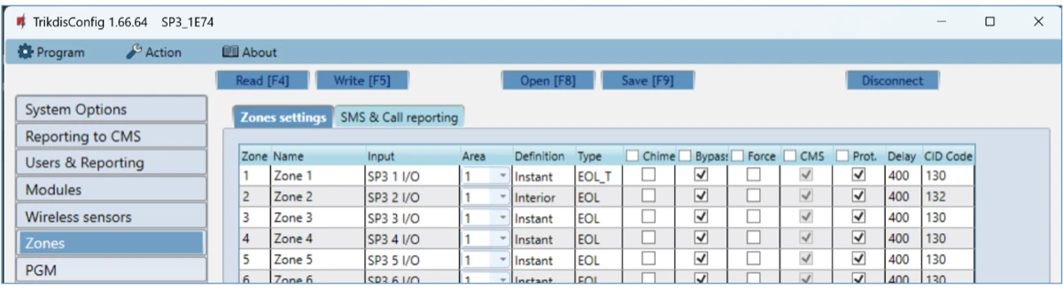
SMS & Call reporting tab – only visible if there is at least one phone number in the Users & Reporting window.
- Zn – the zone's number and the kind of event: Event (alarm) or Restore.
- User / SMS and Call – per user you tick whether they receive an SMS and/or a call about the zone's event.
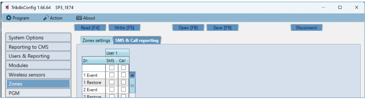
6.8 PGM
Outputs tab:
- PGM No – the PGM output's number.
- Name – the output's name.
- PGM output – which OUT output of the panel or an expander belongs to the PGM.
- Area – the output's partition.
- Output definition – the output's operation:
- Siren – for a siren.
- Remote control – for switching an external device (from the app, by SMS, by call, with a reader).
- Fire Sensor Reset – for resetting the fire detectors after an alarm.
- System State – for a status indicator, for example an LED showing whether the system is armed.
- Flash – for a flasher: continuous when armed, pulsed signal on alarm, stops on disarming.
- Thermostat – thermostat mode. A temperature sensor is needed on the panel; you enter the temperature to maintain on the Thermostat tab.
- Buzzer – repeats the keypad's sound signals.
- Pulse time, s – the on time for pulsed operation, 0–9999 s.
- CMS, Prot. – a report on the output switching on and off goes to the monitoring station and to the Protegus cloud respectively.

Set Action tab – what switches the output:
- ID – the row number.
- Enable – enabling the rule.
- PGM No. – the controlled output, which is switched by the event described in the Factor, Factor No., Start when and Set value columns.
- Action – PGM OFF (switches off), PGM ON (switches on), Pulse OFF (normally on, off for the Pulse time), Pulse ON (normally off, on for the Pulse time).
- Pulse time, s – 0–9999 s.
- Factor, Factor No. – the triggering event and its number: Zone, Sensor, Jamming, Sensor lost, iButton, Arm, Disarm, SMS received, Zone(follow), Stay, Sleep, AC lost, Low battery, Zone tamper. A schedule can also be assigned to the output – the schedule shows when the output should be on; up to ten different ones can be created on the Scheduler tab.
- Start when – an additional condition for the triggering event.
- Set value – the value depending on the condition: the text of a received SMS, a voltage or a temperature. If the panel recognises this value, it performs the action selected in the Action column. For SMS, you separate the keyword switching the output from the rest of the received message with
%signs:%text%– the message contains the text (for example%hoUSe%: the message contains "hoUSe", as in the messageVacationhoUSe25864);text%– the message starts with it (for examplehoUSe%: the message starts with "hoUSe", as inhoUSeddss);%text– the message ends with it (for example%hoUSe: the message ends with "hoUSe", as in1144hoUSe). The text is case-sensitive.

Control tab:
- Entry/Exit control group: Reader – the readers that can be connected (iButton, Wiegand 1 on the G/Y terminals, Wiegand 2 on the IO terminals); En – the reader may control an output; Code – the action (switching the PGM output or controlling the panel) can also be performed with a user code; PGM – the controlled output (it must be in Remote control mode); PGM mode – Pulse or Level; Area action – what should happen to the system's arming state when a key or card is touched to the reader.
- Paradox keypad control group: Utility key – holding the keypad's utility key for 3 seconds switches the output: for the pulse time (Pulse) or it toggles (Level).

Scheduler tab – ID, Enable, Start time (switching on), Stop time (switching off), Mon – Sun (days).
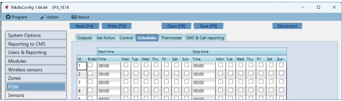
Thermostat tab – ID; PGM No. (the controlled output); Action (heating or cooling); Active (the thermostat works with the selected sensor); Sensor No (the temperature sensor); Temperature (the temperature to maintain).
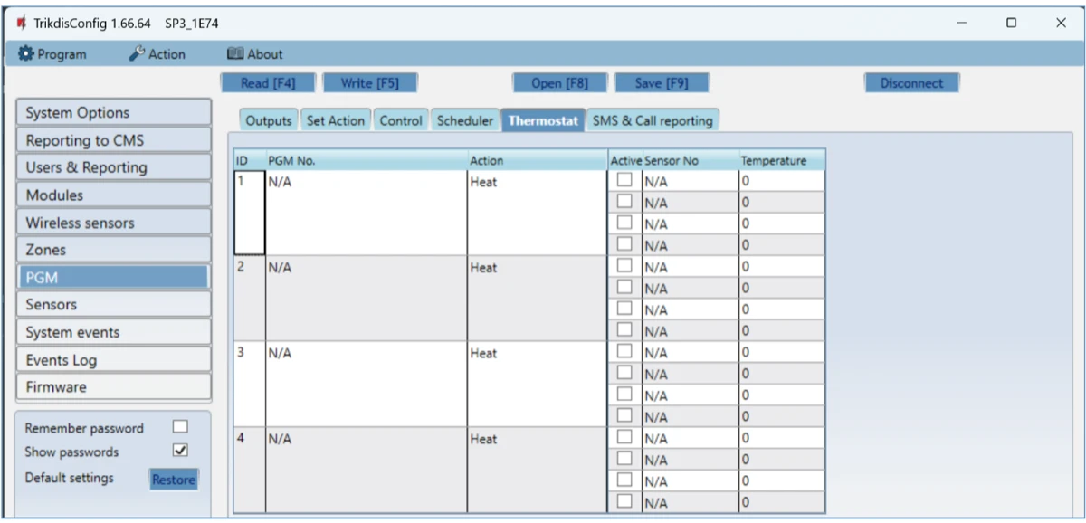
SMS & Call reporting tab – only visible if there is a user phone number, and can only be set for the first eight users. PGM – the output's number and the kind of event (Event – switching on, Restore – switching off); User / SMS and Call – who receives an SMS and/or a call.
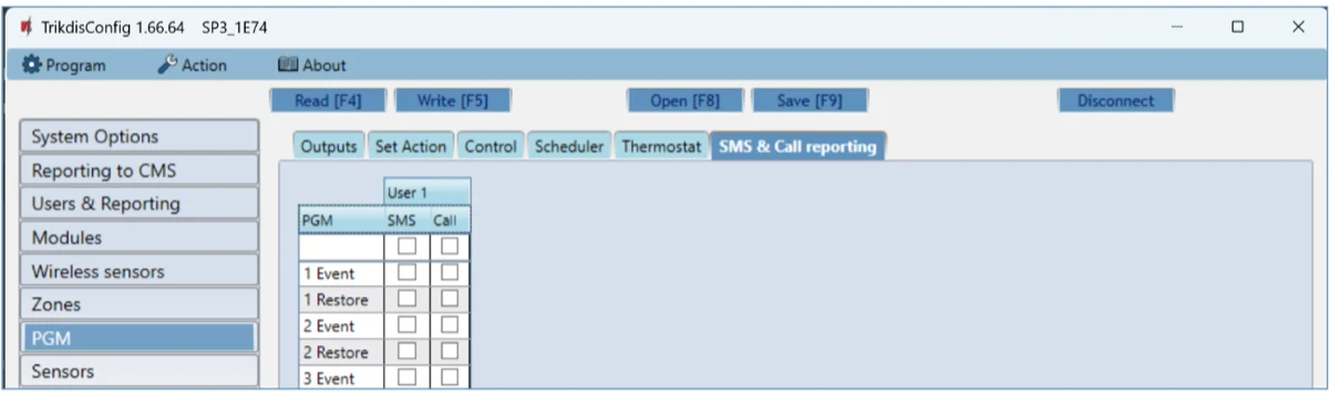
6.9 Sensors
- ID – the temperature sensor's number.
- Module type – the sensor assigned to the ID.
- Serial No. – the serial number of the sensor connected to the panel.
- Sensor name – the sensor's name.
- Max – at a temperature above this an event is generated if High is ticked.
- Min – at a temperature below this an event is generated if Low is ticked.
- Delay, min – the event is only sent if the limit has been exceeded for this many minutes.
- Sensor type – Dallas 1-Wire: up to eight sensors, recognised automatically; Humidity & Temperature (AM23xx series): one AM2301 humidity and temperature sensor, which has to be selected manually in the Module type column.

6.10 System events
Events tab:
- ID – the event's number.
- Event name – the event's name.
- Enable – monitoring and reporting the event.
- CMS, Prot. – reporting to the monitoring station and to the Protegus cloud respectively.
- CID Code – the event's Contact ID code.
- SMS event text, SMS restore text – the SMS text of the event and of the restore.

SMS & Call reporting tab – only visible with a user phone number. ID – the event's number and kind (Event, Restore); Event SMS text – the text of the SMS; User / SMS and Call – who receives an SMS and/or a call.

6.11 Events log
- Read Log – reading the event log from the panel's memory.
- Clear Log – deleting the log.
- The table's columns: Event No., Time, CID code, Event definition. The log shows up to 1000 events.
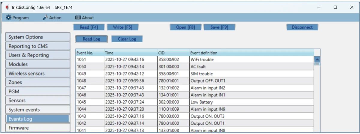
Troubleshooting from the log
With a disputed alarm, read the log first: it shows which zone signalled, when and with which code, and whether the report was sent.
6.12 Restoring the factory settings
To restore the factory settings, click the Restore button in the Default settings group at the lower left of the TrikdisConfig window. Restoring deletes all settings – including the codes and passwords – so save the settings to a file beforehand (Save [F9]).
With the installer code it is only possible if the administrator has not disabled it on the System Options → Access tab (6.2.6).

After restoring
The codes return to their factory values (6.2.6); the SIM PIN, the APN, the WiFi data, the users and the zones are deleted. If you saved the settings to a file beforehand (Save [F9]), you can load them back with the Open [F8] and Write [F5] buttons.
7. Remote programming
TrikdisConfig can reach the "FLEXi" SP3 not only over a USB cable but also remotely, through the Protegus cloud: you can change the settings of a panel that is already installed, read out the event log and even update the firmware without going out to the site.
Remote access requires:
- The panel must be switched on and have a network connection: the PWR LED flashes green, with the mobile network the NET LED is steady green, with Wi-Fi the MOD LED, with Ethernet the ETH LED is steady green (section 1.6). On a modem version the SIM card is active, and the PIN request is switched off or the PIN has been entered.
- The Protegus cloud must be enabled – set it in the Users & Reporting window during the first commissioning over USB (section 6.4).
- You need to know the panel's unique identifier (IMEI / Unique ID – shown on the label on the board and the box, and in the TrikdisConfig status bar) and the administrator or installer code.
Steps:
- Start the TrikdisConfig software.
- In the Remote access section, type the panel's unique identifier into the Unique ID field.
- Optionally give the system a name in the System name field – the program remembers it, and next time you can choose it from the drop-down list.
- Press the Configure button.
- In the window that opens, click the Read [F4] button and enter the administrator or installer code. With the Remember password tick, the program remembers it.
- Make the changes, then send them to the panel with the Write [F5] button.
Remote programming can also be started from the Protegus 2 app with the installer password; for the detailed settings, however, TrikdisConfig is needed. Over the mobile network, the remote connection uses data traffic – several megabytes for a firmware update.
8. Checking the system's operation
After wiring and programming, always check the whole chain: detector → panel → monitoring station and/or Protegus 2.
- Look at the LEDs. The PWR LED should flash green without red flashes, the network LED (NET, MOD or ETH) should be steady green, and the DAT LED should go out once the events have been sent (section 1.6). If PWR flashes red, look for the fault according to chapter 10.
- Trigger an event. Arm and then disarm the system on the keypad, or violate a zone with the system armed so that an alarm is generated.
- Check that it arrives. The event should appear in the monitoring software and/or in the event list of the Protegus 2 app – with the correct partition, zone and user number. In the panel's own log (Events log, section 6.11) you can also see whether the event was generated and whether it was sent.
- Zones one by one. Violate all zones in turn (opening, motion, the smoke detector's test button, tamper), and check that the correct zone signals on the keypad and in Protegus 2.
- Outputs. Switch the PGM outputs remotely from Protegus 2, and check that the device connected to them (siren, indicator light, relay) really operates.
- Remote arming. If the system is also controlled remotely, arm and disarm it from the Protegus 2 app as well, and watch whether the keypad's status follows.
- Power failure. Disconnect the mains power: the panel should keep running on the battery, and the AC Fault event should arrive, then after switching back on the AC Restore event (section 2.2).
By default the panel does not send to the monitoring station (section 6.3), but the Protegus cloud is switched on by default. If the monitoring station receives no events, first check the Reporting to CMS settings and whether the PWR LED flashes 4 or 5 times.
9. Firmware update
Which file should you choose?
The firmware file name is SP3_yxxz_NNNN.fw (section 1.7). The digit y is the hardware version: only the file belonging to the panel's own version can be loaded; with another version the program reports an error. The digit z is the type of wireless detectors – 4 for the MAXIMUM (RF-LORA) and S8 (RF-S8) detectors, 1 for the Paradox RTX3 –; choose it to match the installation; the number of zones that can be handled (32 or 64) also depends on it. The rules for choosing are described in the article FLEXi SP3 firmware: how to choose the right one?.
You can update the firmware yourself – to a newer version and, if necessary, to an older one as well. All device settings remain unchanged after the update.
- Start the TrikdisConfig software and connect the device with a USB cable, or open its programming remotely.
- If newer firmware is available, the software offers to download it – accept it.
- Select the Firmware page and click the Open firmware button. Select the firmware file.
- Press the Update [F12] button, wait for the update to finish, then click OK in the pop-up window. Do not unplug the cable or interrupt the connection in the meantime.
The firmware files are in the TrikdisConfig installation folder, inside the Firmwares subfolder, in the folder named after the device. If there is no such folder, either there is no update for it or the TrikdisConfig software itself needs to be updated. The latest files can also be downloaded as a registered user from the device's page on the manufacturer's website.
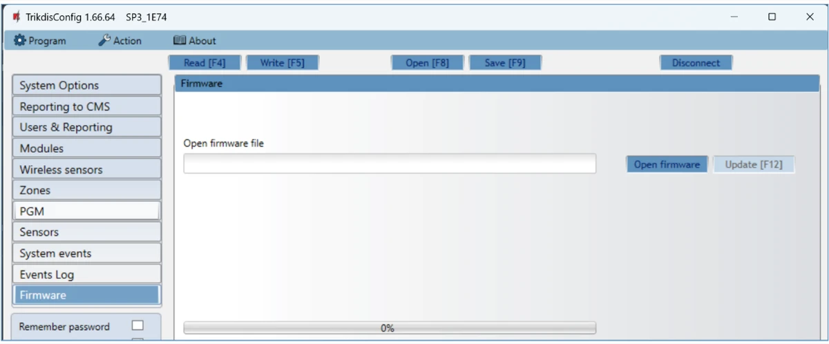
After connecting, TrikdisConfig automatically offers to update the firmware if a newer version exists; this requires an internet connection. An antivirus program or firewall may prevent the automatic firmware download; in that case allow TrikdisConfig, or download the file manually (from the manufacturer's website, after registration) and open it on the Firmware page. At the end of the update click the Write [F5] button, and only then unplug the USB cable.
10. Troubleshooting and frequently asked questions
The most common questions and faults, starting from the board's LEDs (the meaning of the LEDs is in section 1.6). If the answer refers to the detailed chapter, you will find the exact location of the setting there.
The PWR LED flashes red – what does the number of flashes mean?
In normal operation the PWR LED flashes green. If there is a fault, it flashes red, and the number of flashes tells you what is wrong:
| Flashes | Fault | Where to look |
|---|---|---|
| 1 | no SIM card | nano-SIM in the slot, contact (2.4, 6.2) |
| 2 | wrong SIM card PIN code | the PIN on the System Options page, or switch off the PIN request in a phone (6.2) |
| 3 | cannot connect to the mobile network | antenna, signal strength (the yellow flashes of the NET LED: 0–5, 3 is already enough), whether the SIM is active |
| 4 | no connection with the monitoring receiver on channel 1 | Reporting to CMS: address, port, TCP/UDP, encryption key, object ID (6.3) |
| 5 | no connection with the monitoring receiver on channel 2 | the same for the backup receiver (6.3) |
| 6 | the internal clock is not set | setting the time on the System Options page (6.2) |
| 7 | the backup power voltage is insufficient | battery and lugs, the battery's age, charging current (2.2) |
| 8 | no mains (AC) power | power supply, circuit breaker, the main power terminal (2.1) |
| 9 | cannot connect to the Wi-Fi network | network name and password, 2.4 GHz network (see the next question) |
The panel does not find the Wi-Fi network
- The Wi-Fi module of the "FLEXi" SP3 connects only to a 2.4 GHz network (802.11 b/g/n, WPA / WPA2). It does not see a 5 GHz network; if the router uses a common name for the two bands, the 2.4 GHz band must be switched on.
- Check the network name and password on the System Options page (6.2), and that the router does not filter devices by MAC address.
- The MOD LED flashes green while connecting, and is steady green once the connection is established.
- In a metal box the Wi-Fi signal can be weak: the panel works reliably with an antenna outside the box, a router close to the box or a stronger signal.
There is a network, but no events arrive in Protegus 2
- The DAT LED is steady yellow if there are unsent messages in the buffer: in that case the connection is the problem, not the settings. Look at the NET / MOD LED and the PWR flashes.
- The connection to the Protegus cloud is enabled by default; if it has been switched off, switch it back on with the Enable cloud service checkbox on the Users & Reporting → Protegus tab (6.4.3). On the Reporting to CMS → Settings tab you can only set which path (SIM, Wi-Fi, LAN) the Protegus traffic takes.
- On the System events page, sending of the event concerned must be enabled (6.10) – what is disabled here, the panel does not send over any channel.
- Is the device connected to the Protegus 2 account (5.1)? To add a new system, the device's unique identifier is needed.
The monitoring station receives no events
- Reporting to the monitoring station is switched off by default; it must be switched on and the receiver's data entered on the Reporting to CMS page (6.3).
- 4 or 5 red flashes of the PWR LED indicate that there is no connection with the receiver on channel 1 or channel 2 respectively: address, port, protocol (TCP/UDP), encryption key, object ID.
- If both the monitoring station and Protegus 2 are set up, the event goes to the receiver first and then to the user – so an event appearing in Protegus 2 does not mean that the receiver has also received it.
Which firmware should I upload? What do the numbers in the file name mean?
The firmware file name is SP3_yxxz_NNNN.fw. The first digit (y) is the hardware version – 1: Wi-Fi + 4G, 2: Wi-Fi, 3: LAN / LAN + Wi-Fi, 5: Wi-Fi + 2G, 6: LAN + 4G –; this cannot be changed when updating, and TrikdisConfig indicates if you have chosen a file that does not match the hardware. The last digit (z) specifies the type of wireless receiver and with it the number of zones: 0 RF-SH (32 zones), 1 Paradox RTX3 (32), 2 Honeywell (64, not used in Europe), 4 MAXIMUM (RF-LORA) or S8 (RF-S8) detectors (64; not needed for the LORA expanders). This may be changed: a different receiver needs firmware with a different z digit (section 1.7 and chapter 9). The four-digit number at the end is the version; as a general rule, use the highest.
How many zones can I have, and what does it depend on?
The board has 10 IO terminals, each of which can be a zone (input) or a PGM output. With zone doubling (ATZ) two detectors can be connected to one terminal, giving 20 zones. With keypads, iO series and LORA expanders, and a wireless receiver, the number of zones can be expanded to 32 or 64 – which of the two is decided by the last digit of the firmware (previous question). The number of partitions is 8.
I am replacing an old panel – do I have to replace the detectors' resistors?
No. In the "FLEXi" SP3 the values of the end-of-line resistors can be set, so the existing detectors can keep the resistors used with the old panel. You set the zone type (NC, NO, EOL, 3EOL, ATZ) and the resistor values on the Zones page (3.2 and 6.7).
I want to connect a larger load (siren, lock, gate) to an output
As an output, the IO terminal is open collector and can be loaded with at most 100 mA – only an indicator light or the coil of a small relay can be connected to it directly. For a larger load, use a relay as described in section 3.8. The BELL output can be loaded with 1 A, the AUX output supplies at most 1 A at 12 V DC to external devices – add up the current requirement of the keypads, expanders and detectors from the table in 1.4, and do not exceed it.
Which keypad can I use, and how many?
The panel supports the Trikdis FLEXi / SK keypads and the listed Paradox and Crow keypads (the list and the current requirements are in section 1.4). On one bus up to 8 keypads, and they must be of the same type. The LED keypads only handle the first two partitions; for more partitions an LCD keypad is needed. The FLEXi LCD keypad stores four languages at a time; if the language you need is not among them, the keypad's firmware has to be updated: https://mobilamb.eu/firmware-update-process-of-the-flexi-lcd-keypad .
I want to use a Paradox RTX3 receiver
For the RTX3, the last digit of the firmware must be 1 (SP3_xxx1_NNNN.fw); you will find the file in the TrikdisConfig installation folder, in the Firmwares\SP3\RTX3 subfolder, and the update procedure in chapter 9. After the change, the Wireless page indicates if no RTX3 is registered yet. The frequency of the RTX3 and the wireless devices must match (433 or 868 MHz) – check this before buying. Details: https://mobilamb.eu/flexi-sp3-supports-the-paradox-rtx3-wireless-expansion-module .
The panel does not reply to SMS commands
- Only the modem versions (2G / 4G) can be controlled by SMS and phone call; a Wi-Fi-only or Ethernet-only panel cannot.
- The message structure and the list of commands are in section 5.3; the factory SMS password is
123456, which is worth changing immediately in the System Options → Access group (6.2). - Only a user whose phone number is in the list of users on the Users & Reporting page can control the panel by call and SMS (6.4).
What must I set in any case at the first commissioning?
Most small and medium-sized systems work with the factory settings, but do not skip these: changing the master code and the installer / administrator access codes (6.2, 6.4), setting the time (6.2), the zones' type and resistors (6.7), the users and their phone numbers (6.4), the monitoring receiver's data, if there is one (6.3), and connecting the system to the Protegus 2 account (5.1). At the end, carry out the check in chapter 8.
11. Warranty and safety instructions
Attention!
Electricity can be dangerous and may cause personal injury or DEATH, as well as other financial loss or damage if not used or installed properly.
Installation involves working with electrical equipment, and it should be executed in accordance with current regulations!
Warranty validation requires the device to be installed by a qualified person following the installation regulations for electrical equipment and adhering to the current regulations for the safe operation of electrical equipment.
11.1 Warranty and limitation of liability
The alarm control panel comes with a warranty of 24 months from the date of purchase; during this time the manufacturer repairs faults originating from it free of charge. The condition of the warranty is that the panel is installed by a qualified person in accordance with this manual and the regulations for electrical equipment, and that it is also operated accordingly. For repair, the panel must be sent in in the manufacturer's packaging, with a description of the fault; after the warranty has expired, maintenance and repair can be requested against payment.
The warranty ends early if
- the panel has been repaired, or an attempt has been made to repair it, by an unauthorised person;
- it has been used for a purpose other than intended;
- it has been stored or installed in an unsuitable place (unsuitable climatic conditions, aggressive chemical environment);
- it has been mechanically damaged or deliberately vandalised;
- it has been damaged by force majeure (for example a lightning strike).
The manufacturer is not liable
- for the panel malfunctioning if it was not installed or used according to the manual;
- for the panel malfunctioning if the cause is a fault or failure of the mobile network or internet connection, or a fault in the provider's network;
- for the restriction, termination or interruption of the mobile network or internet service or of the power supply, or for any material or non-material damage resulting from it;
- for any material or non-material damage suffered by the buyer or the user as a result of robbery, burglary, theft, fire or another loss event.
11.2 Safety instructions
- Read this manual before using the panel. The "FLEXi" SP3 is electrical equipment: it may only be installed and serviced by a qualified person, in compliance with the manual and the regulations for installing electrical equipment.
- The panel must be de-energised during installation; disconnect it from the power before every connection and servicing: from the mains with the circuit breaker, from the battery by pulling off the lugs.
- Mount the panel in a place locked away from unauthorised persons, at a safe distance from sensitive electronic equipment. The board is not resistant to vibration, mechanical impact, moisture or aggressive chemical environments; it meets environmental class II of the EN 50131 standard.
- The box, the transformer, the battery and the programming device must meet the safety requirements of EN 60950.
- The panel works from the 230 V, 50 Hz mains through a Class II step-down transformer (16–18 V AC) or from a 16–24 V DC power supply; a 12 V battery with a capacity of at least 7 Ah is needed as backup power. The current consumption depends on the connected external devices (section 2.1).
- A two-pole automatic circuit breaker with a contact gap of at least 3 mm must be installed in the power circuit; the switch must be in a place known to and accessible by the technician servicing the panel.
- Faults resulting from improper installation or use, as well as modifications and repairs not authorised by the manufacturer, void the warranty.
- Follow local waste disposal regulations: do not throw a faulty device, the battery or the components in household waste.
See also
- FLEXi SP3 firmware: how to choose the right one? – the meaning of the hardware and receiver codes, which firmware is for which system.
- FLEXi SP3 + Paradox RTX3 wireless expansion module – Paradox wireless detectors with the SP3.
- RF-S8 transceiver and S8 detectors – installation and pairing manual – the S8 wireless devices with the SP3: wiring, firmware, pairing.
- Flexible wireless access control with the GATOR RF-LoRa system – the RF-LORA and iO-LORA modules in a system.
- The Trikdis FLEXi SP3 has obtained GRADE 3 certification – what the certification means.
- Trikdis FLEXi SP3 – introducing the smart alarm control panel – presentation of the panel, replacing an old panel.
- Firmware update procedure of the FLEXi LCD keypad – the keypad's languages and updating it.
- Trikdis FLEXi Keypad SK-LED button keypad – short user guide and SK-LCD button keypad – short user guide – for the user.
- Remote arming with a keyswitch from the Protegus 2 app – if the SP3's PGM output arms another panel.
- Adding an IP camera to Protegus 2 – live view on the Protegus 2 home screen.
- Documentation: docs.trikdis.com – Security control panel "FLEXi" SP3.