

W485 WiFi and E485 Ethernet module – installation and setup manual
Manual for the Trikdis W485 WiFi and E485 Ethernet modules: compatible devices, connection to the RS485 bus, setup in TrikdisConfig, reporting to the monitoring station and the Protegus 2 app over wired or WiFi internet.
- 21 min read

1. Overview
The W485 is a WiFi module that adds a wireless internet communication channel to Trikdis devices. With the G16 and G16T communicators, which work over GSM / IP channels, it can act as the primary communication channel – all control and notifications go through it, so the alarm system can be armed or disarmed remotely via the W485 module. As long as the WiFi channel is available, communication does not go through the SIM card.
The E485 Ethernet module adds a wired internet communication channel to Trikdis communicators. With certain devices it can even work as the primary communication path, so remote control of the alarm system and notifications go over the wired internet connection. For the GV17 gate controller and the G16 and G16T communicators, which work over GSM / IP channels, this means that all control and event handling goes through the E485 as long as wired internet is available, so communication does not rely on the SIM card's data usage.
Both modules also work as the primary channel with the G17F fire alarm communicator and the CG17 security control panel, and the E485 can be connected to the FLEXi SP3 alarm control panel. With the T16 radio communicator, the module takes over forwarding of the messages (section 1.3).
Both the W485 and the E485 communicate with the monitoring station and the user at the same time – the user is notified of the alarm system's events in real time through the Protegus 2 mobile and web app.
In short
- E485 – wired Ethernet (RJ45 connector).
- W485 – WiFi 2.4 GHz (WPA / WPA2): a good choice where no UTP cable has been run.
- The internet is the primary channel: as long as it is up, everything goes over it. If it drops, the device switches to the mobile network by itself, and as soon as the internet is back, it returns to IP.
- Not just reporting: the Protegus 2 app (notifications, remote control) also works over this channel.
- Can also be used without a SIM card if needed – with the GV17, the G17F, the CG17 and the FLEXi SP3 (section 1.3).
- Connection: on the RS485 bus, powered from the same supply as the main device (module power input 9–28 V DC); no separate power supply is needed.
- Setup: with the TrikdisConfig software, over USB, through the main device (chapter 3).
1.1 Main features
- WiFi (W485) or wired (E485) internet communication.
- The user is notified of the alarm system's events in the free Protegus 2 mobile and web app, also by push notification.
- Free Protegus 2 server, so neither a fixed IP address nor dynamic DNS (DynDNS) is needed.
- The module forwards the messages of the designated systems to the monitoring station over IP, in Contact ID code format.
- If the connection on the primary channel is lost, it automatically switches to the second, backup channel.
- If the internet connection is lost, it automatically switches back to the original device's communication channel.
1.2 How does it work?
The W485 sends the main device's messages over the local WiFi network, through the internet router, to the monitoring station (CMS – central monitoring station) and the Protegus 2 app; the E485 does the same over wired internet, through an Ethernet cable plugged into the router. As long as the WiFi or wired connection is up, the main device communicates over it and does not use the mobile data connection. If the connection drops, it sends the messages over the mobile network, and returns to the module when the connection is restored.
The FLEXi SP3 panel also receives control commands over the E485; with it, you set the order of the channels (SIM, WiFi, LAN – E485) yourself (section 3.2.3).
If you disable the SIM card's mobile data in the main device (GV17, G17F: Disable the use of SIM card mobile data, section 3.2.2), data goes only through the module; if the internet drops, the main device stores the events in its memory and sends them when the connection is back.
1.3 Compatible devices
| Main device | W485 | E485 | What does the module provide? | SIM card in the main device |
|---|---|---|---|---|
| G16 (3G / 4G version) | yes | yes | full communication: monitoring station, Protegus 2 (notifications, remote control) | required |
| G16T | yes | yes | full communication | required |
| GV17 GATOR (from firmware 1.06) | yes | yes | full communication | not required – without a SIM it can only be controlled from the app; no calls or SMS |
| G17F (from firmware 1.08) | yes | yes | full communication | not required |
| CG17 (from firmware 1.13) | yes | yes | event messages to the monitoring station and to Protegus 2 | not required – without a SIM there is no mobile network backup; no calls or SMS |
| FLEXi SP3 | – | yes | reports and control commands; the order of the channels can be set | not required |
| T16U / T16V | yes | yes | forwarding of messages to the monitoring station and to Protegus 2 | – (the T16 has no SIM) |
For the CG17, wiring and setup are described in sections 3.16–3.17 and 4.5.1–4.5.2 of the CG17 security control panel manual.
The module cannot be connected to the 2G G16 (G16_G410): the 2G version has no RS485 bus.
1.4 Technical specifications
| Parameter | W485 | E485 |
|---|---|---|
| Communication channel | WiFi / IP, 802.11 b/g/n, 2.4 GHz; WPA, WPA2, WPA mixed | Ethernet / LAN / IP, IEEE 802.3, 10Base-T, RJ45 connector |
| Connection to the main device | RS485 | RS485 |
| Transmission protocol, encryption | TRK_TCP, TRK_UDP | TRK_TCP, TRK_UDP |
| Event transmission | Contact ID code | Contact ID code |
| Periodic test report | yes | yes |
| Protegus users | unlimited | unlimited |
| Mobile and web app, push notifications | yes | yes |
| Supply voltage | 9–28 V DC | 9–28 V DC |
| Current consumption | 50 mA in standby, up to 150 mA | 50 mA in standby, up to 150 mA |
| Operating environment | −10…+50 °C, relative humidity up to 80 % (at +20 °C) | −10…+50 °C, relative humidity up to 80 % (at +20 °C) |
| Terminal block | detachable | detachable |
| Dimensions | 88 × 62 × 26 mm | 88 × 62 × 26 mm |
| Weight | 80 g | 80 g |
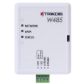 Trikdis W485 Wifi module (RS485)
 Trikdis E485 Ethernet module (RS485)
1.5 Terminals
| Terminal | Description |
|---|---|
| +DC | positive supply terminal (9–28 V DC), from the same supply as the main device |
| −DC | negative supply terminal |
| A 485 | RS485 bus – to the main device's A 485 terminal |
| B 485 | RS485 bus – to the main device's B 485 terminal |
| RJ45 (E485 only) | Ethernet connector for the LAN cable coming from the router (switch) |
The module's 6-digit serial number (SN) is on the module housing and on its box; you need it for the setup (section 3.1).
2. Wiring
Warining!
It is forbidden to perform wiring on a device under voltage. Before starting the work, disconnect power (including backup batteries).2.1 Before wiring
- The module connects to the main device's RS485 bus: the main device's A 485 terminal goes to the module's A 485 terminal, and B 485 to the module's B 485 terminal.
- The module is powered from the same supply as the main device (+DC, −DC); no separate power supply is needed. The module's power input is 9–28 V DC.
- The RS485 connection can be up to 100 m long. If the bus is longer than 1 m, use twisted-pair cable (STP 4x2x0.5), and do not run it in parallel with mains (AC) power cables or other sources of strong electromagnetic fields.
- The LAN cable from the router (switch) goes into the E485's RJ45 connector. The W485 needs a 2.4 GHz WiFi network (WPA or WPA2).
The “up to … m” distances are theoretical maximums achievable under ideal conditions. In practice, the quality and routing of the cable, sources of interference and, for radio links, walls and terrain give a considerably shorter range. Plan with a margin, and on long runs check the connection during commissioning.
| Main device | Common power supply | RS485 terminals on the main device |
|---|---|---|
| G16 (3G / 4G), G16T | power supply, 12 V DC, at least 0.5 A → +DC, −DC | A 485, B 485 |
| G17F | power supply, 12 V DC, 0.5 A → +DC, −DC | A 485, B 485 |
| GV17 GATOR | power supply, 10–28 V DC, 0.5 A → AC/+DC, AC/−DC | A 485, B 485 |
| FLEXi SP3 (E485 only) | the panel's AUX+ (+12 V) and AUX− terminals | 485 A, 485 B |
| T16U / T16V | the alarm panel's +AUX (+12 V) and −AUX terminals, shared with the T16 | A 485, B 485 |
The wiring diagrams for the T16U / T16V radio communicator are in section 2.6 of the T16U / T16V manual.
2.2 Wiring to the G16 (G16T, G17F, GV17)
The diagrams show the G16. The G16T and G17F terminals are the same; the GV17 GATOR's power terminals are AC/+DC and AC/−DC (section 2.1, table).


These diagrams are also in the communicators' own manuals: G16 manual and G16T manual (sections 3.7–3.8), GV17 GATOR manual (sections 2.7–2.8).
2.3 Wiring to the FLEXi SP3 panel (E485)
The E485 can be connected to the FLEXi SP3; the panel powers the module from its own AUX output.

- 1 LAN cable
The “up to … m” distances are theoretical maximums achievable under ideal conditions. In practice, the quality and routing of the cable, sources of interference and, for radio links, walls and terrain give a considerably shorter range. Plan with a margin, and on long runs check the connection during commissioning.
With the E485, the panel does not need a SIM card. Details: FLEXi SP3 manual (section 3.9).
3. Setup in TrikdisConfig
You add and configure the W485 and the E485 in the TrikdisConfig window of the main device. The steps are similar for every main device; only the names of the pages and tabs differ.
All Trikdis devices can be programmed using a common software. The software is called TrikdisConfig and can be downloaded from the manufacturer's website.
After downloading, install the program. If a new version is available each time you start TrikdisConfig, download and install the recommended update!
- Connect the main device to the computer with a USB cable, start TrikdisConfig, and read the settings with the Read [F4] button.
- Add the module to the module list with its serial number (section 3.1).
- Enter the network settings (section 3.2).
- Write the settings with the Write [F5] button, and check that the main device has found the module (section 3.1, chapter 4).
3.1 Adding the module to the list
Open the modules page, choose a free row, select the module from the Module drop-down list (Module Type on the G16 and G16T), and enter the module's 6-digit serial number in the Serial No. field – you will find it on the sticker on the module housing and on the box (SN).
| Main device | Page and tab | Module name in the list |
|---|---|---|
| G16, G16T | RS485 modules → Modules list | W17u/W485, E485 |
| GV17 GATOR | Modules → Modules | W485 (W17u) module, E485 communicator |
| G17F | Modules → RS485 modules | W485 (W17u) module, E485 communicator |
| FLEXi SP3 | Modules → RS485 modules | E485 communicator |

- G16, G16T: after selecting the module and entering the serial number, press Write [F5], unplug the USB cable, and wait one minute while the communicator registers the module. Then plug the cable back in and read the device (Read [F4]): the module's own numbered tab appears on the RS485 modules page (for example Module 1 W485).
- GV17 GATOR: after selecting the module and entering the serial number, the Parameters tab with the module's settings appears.
- G17F, FLEXi SP3: when the main device has found the module, the module's firmware version appears in the Firmware version column – this is the sign that the module is alive.
For the T16U / T16V radio communicator, adding and configuring the module is described in section 3.4 of the T16U / T16V manual.
3.2 Network settings
The module's network fields are the same for the main devices above:
- DHCP mode – automatic setup: the module gets its IP address, subnet mask and gateway from the router (DHCP in the G16 and G16T list, a checkbox elsewhere). For manual setup (G16, G16T: Static; elsewhere unchecked), fill in the three fields below.
- Static IP – the module's fixed IP address on the local network: an address that no other device uses and that is outside the router's DHCP range.
- Subnet mask – the network's subnet mask.
- Default gateway – the default gateway, usually the router's address.
- Wifi SSID name, Wifi SSID password (W485 only) – the name and password of the 2.4 GHz WiFi network.
3.2.1 G16 and G16T
On the module's numbered tab there is also a table below the network fields: you can assign a Contact ID code to the RS485 bus fault (BUS_FAULT – the connection between the module and the communicator is lost, then restored) (Enable, E/R, CID, Part., Zone). The event is received by both the monitoring station and Protegus 2.


For the W485 and the E485 to work, the G16's or G16T's monitoring station and/or Protegus connection must be set up (section 3.3), and there must be a SIM card in it. As long as the WiFi or wired connection is up, the communicator communicates over it and does not use the mobile data connection.
3.2.2 GV17 GATOR and G17F
On the GV17 you enter the settings on the Parameters tab after selecting the module; on the G17F on the W485 settings or E485 settings tab. The fields of the Communicator network settings group are described in section 3.2; in the SIM parameters group you set how the main device uses the SIM card alongside the module:
- Disable indication of the absence of a SIM card – when checked, the main device does not report a fault if there is no SIM card in it (for SIM-free, internet-only use).
- Use dial and SMS when working over internet module – when checked, control by call and SMS also works alongside the module. When unchecked, the main device does not use calls and SMS while the internet connection is up; if the internet drops, calls and SMS work again, and the main device sends an SMS to the users.
- Disable the use of SIM card mobile data – when checked, the main device does not use the SIM card's mobile data; data goes only through the module. If the internet drops, the main device stores the events in its memory and sends them through the module once the internet is back.


The GV17's module settings are also in its own manual: GV17 GATOR manual, section 5.4.
3.2.3 FLEXi SP3
The E485 settings are on the Modules → E485 settings tab: DHCP mode, or for manual setup Static IP, Subnet mask and Default gateway (section 3.2).

You set which path the panel communicates over on the Settings tab of the Reporting to CMS page, in the Reporting mode group: Main type, Backup type, Backup type 2 – SIM, WiFi or LAN(E485), separately in the CMS and Protegus columns. The order matters: if the Main type connection cannot be established, the panel switches to the Backup type, then to the Backup type 2 path. If the E485 is to be the primary path, set Main type to LAN(E485).
Details: FLEXi SP3 manual, sections 5.3 and 5.5.
3.3 Monitoring station and Protegus 2
The module carries the connections set in the main device: you set the monitoring receiver's address, port and protocol, and the Protegus 2 connection, on the main device's pages; the module's tabs have no fields for these. (The T16U / T16V is different: there you enter the receiver and the Protegus connection on the module's tab – T16U / T16V manual, section 3.4.) If they are not set up yet:
| Main device | Protegus 2 | Monitoring station (CMS) |
|---|---|---|
| G16 | G16 manual, section 2.1 | section 2.2 |
| G16T | G16T manual, section 2.1 | section 2.2 |
| GV17 GATOR | GV17 GATOR manual, section 5.5 (IP Reporting, Cloud application) | section 5.5 |
| FLEXi SP3 | FLEXi SP3 manual, section 4.1 | section 5.3 |
4. Checking operation
At the end of wiring and setup, test the whole chain: main device → module → monitoring station and/or Protegus 2.
- The main device sees the module. On the G17F and the FLEXi SP3, the Firmware version appears in the module's row on the Modules page; on the G16 and G16T, the module's numbered tab is there after reading (section 3.1).
- Event through the module. Arm and then disarm the system, or trigger another event, and check that it has arrived in the monitoring software and/or in the event list of the Protegus 2 app.
- Testing the switchover. Unplug the LAN cable from the E485, or switch off the WiFi router (W485), and trigger another event: if there is a SIM card in the main device, the event must still arrive, over the mobile network. Then reconnect the cable or switch the router back on, and check that events keep arriving properly afterwards.
- Protegus 2. If the main device can also be controlled from the app, arm and disarm the system (on the GV17, open the gate) from the Protegus 2 app as well.
If you checked Disable the use of SIM card mobile data in the GV17 or the G17F, the event in step 3 does not go over the mobile network: the main device stores it and sends it through the module once the internet is back (section 3.2.2). The BUS_FAULT event set in the G16 and G16T reports the loss of the connection between the module and the communicator to the monitoring station and to Protegus 2 (section 3.2.1).
5. Frequently asked questions
Does the main device need a SIM card?
On the G16 and G16T, yes: with them the module needs a SIM card to work. The GV17 GATOR (from firmware 1.06), the G17F (from firmware 1.08), the CG17 (from firmware 1.13) and the FLEXi SP3 can also be used with the module without a SIM card; in that case the GV17 can only be controlled from the app, with no calls or SMS, and the CG17 has no mobile network backup, calls or SMS. If there is a SIM card, the mobile network is the backup path: when the internet fails, messages go over it.
Does the W485 work with 5 GHz WiFi?
No: the W485 connects to a 2.4 GHz network (802.11 b/g/n; WPA, WPA2 or mixed encryption). With a dual-band router, the 2.4 GHz band must be switched on.
Does the module need a separate power supply?
No: the module is powered from the same supply as the main device; its power input is 9–28 V DC. Its current consumption is 50 mA in standby, up to 150 mA – take this into account when sizing the common power supply or the load on the panel's AUX output.
How far can the module be from the main device?
The RS485 connection is up to 100 m (section 2.1). So the W485 can go where the WiFi signal is good, and the E485 near the router or the network socket – the main device can stay where it is. Above 1 m, use twisted-pair (STP) cable.
Do I need a fixed IP address, dynamic DNS or port forwarding on the router?
No. The Protegus 2 connection works through the free Protegus 2 server, so neither a fixed IP address nor dynamic DNS (DynDNS) is needed. The main device builds the connection outwards, towards the monitoring receiver and the Protegus cloud, so no port needs to be opened on the router either. On a filtered network – corporate, institutional – outgoing traffic to the receiver's address and port and to the Protegus cloud must be allowed; agree this with the system administrator in advance.
W485 or E485 – which should I choose?
Where you can run a UTP cable from the router, the E485 is the more stable choice: a wired connection is not affected by a weakening WiFi signal. Where no cable has been run but the 2.4 GHz WiFi is good, the W485 is the convenient solution. Only the E485 can be connected to the FLEXi SP3.
Can a W485 be connected to the FLEXi SP3?
No: only the E485 is in the SP3's module list (E485 communicator). The WiFi versions of the SP3 have WiFi built in (FLEXi SP3 manual, chapter 1).
Can the module be connected to the 2G G16?
No: the G16 with a 2G modem (G16_G410) has no RS485 bus. The module works with the 3G / 4G version of the G16.
What should I do if the main device does not see the module?
- Check the serial number: the 6-digit number (SN) on the module's sticker.
- Check that the A and B wires are not swapped and that both go to the correct terminal (section 2.1, table).
- Check that the module has power (+DC, −DC) and that the negative poles of the two devices are common.
- On the G16 and G16T: after adding the module, did you write to the device, unplug the USB cable and wait one minute before reading it again (section 3.1)?
- Check that the main device's firmware is new enough: GV17 GATOR from 1.06, G17F from 1.08, CG17 from 1.13.
What should I do if the module does not connect to the network?
- With DHCP, check in the router whether the module has received an IP address; with manual setup, check the IP address, the subnet mask and the gateway (section 3.2).
- On the W485, check the WiFi network name and password, and that the router's 2.4 GHz band is switched on.
- On the E485, check the LAN cable and the router (switch) port.
- On a filtered network, check that outgoing traffic is allowed (see above, in the question about port forwarding).
6. Safety instructions
Attention!
Electricity can be dangerous and may cause personal injury or DEATH, as well as other financial loss or damage if not used or installed properly.
Installation involves working with electrical equipment, and it should be executed in accordance with current regulations!
Warranty validation requires the device to be installed by a qualified person following the installation regulations for electrical equipment and adhering to the current regulations for the safe operation of electrical equipment.
- The W485 and the E485 may only be installed and maintained by qualified persons.
- Before wiring, read this manual and the main device's manual.
- Disconnect the power before making any connection – of the main device, the power supply and the battery as well.
- Changes, modifications or repairs not authorized by the manufacturer void the warranty.
- Follow local waste disposal regulations: do not throw the device in household waste – hand in the discarded device as electronic waste.
See also
- G16 communicator manual and G16T communicator manual – wiring the module (sections 3.7–3.8) and the RS485 modules window (G16: section 6.7, G16T: section 6.6).
- GV17 GATOR manual – W485 and E485 (sections 2.7–2.8 and 5.4).
- CG17 security control panel manual – W485 and E485 (sections 3.16–3.17 and 4.5.1–4.5.2).
- FLEXi SP3 alarm control panel manual – E485 (sections 3.9, 5.3 and 5.5).
- T16U / T16V manual – RS485 modules (sections 2.6 and 3.4).
- Trikdis W485 WiFi module and Trikdis E485 Ethernet module – the product pages.