

E16 communicator – installer and user manual
Installer and user manual for the Trikdis E16 Ethernet communicator: connection to the alarm control panel's data bus or serial port, programming the panel, network setup in TrikdisConfig, reporting to the monitoring station, Protegus 2 app.
- 61 min read

1. Overview
The E16 is Trikdis's direct-connection Ethernet communicator: it does not connect to the alarm control panel's telephone line output, but to the panel's keypad bus or serial port. It reads the events directly from the panel – together with the zone, partition and user number – and forwards them over the local network and the wired internet connection to the monitoring receiver, as well as to the Protegus cloud and the user's app. It works with the supported DSC, Paradox, UTC Interlogix (Caddx), Texecom, Pyronix, InnerRange, Honeywell and Crow panels; with the directly controllable types, the user arms and disarms from the Protegus 2 app with their own keypad code, without a separate keyswitch zone. For panels of other makes that only have a telephone line output, the E16T (TIP/RING) Ethernet communicator is the right choice; where there is no wired internet, the G16 cellular communicator.
1.1 What it is for and how it works
- It reads the panel directly. On the panel's bus, every event reaches the communicator immediately, with the panel's own numbering; the panel's dialer does not need to be set up, and there is no Contact ID dialing either.
- It reports to the monitoring station. It sends the events over an IP connection to a Trikdis software or hardware receiver (TRK protocol; Trikdis receivers work with any monitoring software) or to any universal receiver (SIA DC-09 2007/2012, SUR-GARD TL150). With a SUR-GARD receiver, the communicator converts the Contact ID codes received from the panel into SIA codes; the conversion table is in the appendix of the English documentation on docs.trikdis.com. By default it checks the connection every 30 seconds (the interval can be changed, section 6.3), and if there is a fault it switches to the backup channel; with a parallel channel, the events can be sent to two receivers at the same time.
- It notifies the user. The Protegus 2 app shows what happened with push notifications, a separate sound alert and an event list; from the app the user can arm and disarm, and switch the connected devices (lighting, gate, heating, ventilation, irrigation system, etc.). Protegus 2 works with the panels of every make supported by the E16.
- It works with the monitoring station and the user together or separately: it can be used with Protegus 2 only (without a monitoring station), with a monitoring station only, or with both. If both are set up, the event is sent to the monitoring station first, then to the user.
- No SIM card or mobile subscription is needed. The device uses the site's existing internet connection: it connects to the router or switch with an Ethernet cable, gets its address via DHCP by default, and only builds outgoing connections, so no port needs to be opened on the router.
- It has its own inputs and outputs. Three dual-function I/O terminals can be used as inputs (detector, tamper) or as controllable outputs (keyswitch zone, relay). With an iO-8 expander connected to the RS485 bus, 8 more I/Os can be added to the system.
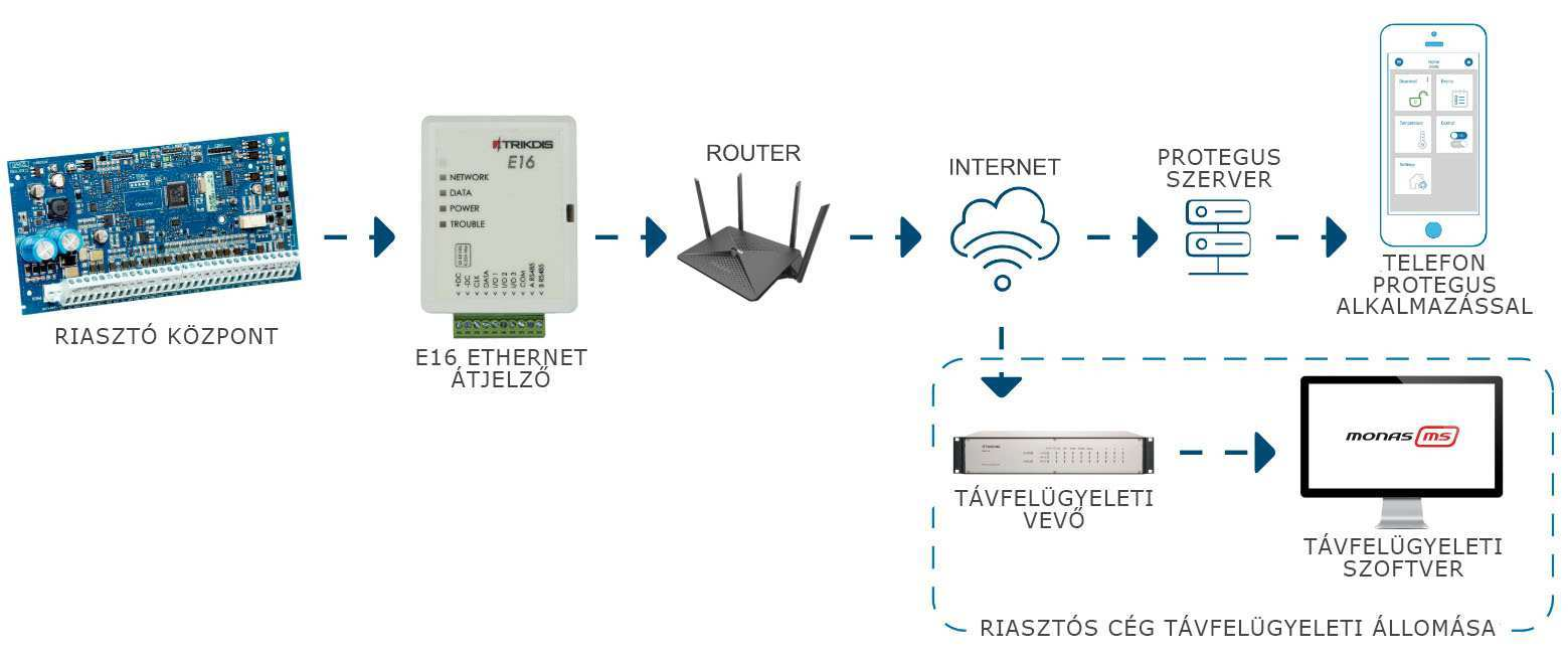
The figure below shows how the system is built up: the alarm panel's bus connects to the E16, the E16 reaches the internet through the router, and from there the Protegus cloud and the monitoring receiver, while the user sees the system in the Protegus 2 app.
1.2 Compatible alarm control panels
The E16 can be connected to the panels below. With the directly controllable types, arming and disarming is done from the app with the keypad code; with the others, with a keyswitch zone (section 3.4). For direct control of Paradox panels, the panel's firmware must be at least V.4; on the newer Paradox types (SP+, MG5050+, EVOHD+) the serial port is locked by default and must be unlocked before use.
Panels that can be controlled directly – the communicator receives the events over the data bus or the serial port, and arming / disarming works without any additional wiring:
| Manufacturer | Connection | Models |
|---|---|---|
| Paradox | serial port | Spectra SP4000, SP5500, SP5500+*, SP6000, SP6000+*, SP7000, SP7000+*, SP65 Magellan MG5000, MG5050, MG5050+*, MG5075 DIGIPLEX EVO192*, EVOHD*, EVOHD+ (* firmware above 7.50) |
| DSC | data bus | PC585, PC1565, PC1616, PC1832, PC1864 |
| Interlogix | data bus | NetworX (Caddx) NX-4v2, NX-6v2, NX-8v2, NX-8e |
| Texecom | serial port | Premier 24, 48, 88, 168, 640 Premier Elite 12, 24, 48, 64, 88, 168, 640 |
| Honeywell | data bus | Ademco Vista-15, Vista-20, Vista-48 |
On the newer Paradox panels marked with *, the serial port is locked from the factory; an external device can only communicate with it after it has been unlocked.
Panels that can be controlled with a keyswitch – the communicator receives the events over the data bus or the serial port; control requires keyswitch wiring and programming (section 3.4):
| Manufacturer | Connection | Models |
|---|---|---|
| Paradox | serial port | Spectra 1727, 1728, 1738 Magellan MG5050E ESPRIT E55, 728ULT, 738ULT DIGIPLEX EVO48 |
| DSC | data bus | PC1404, PC5020 |
| Texecom | serial port | Premier 412, 816, 832, 832+ |
| Inner Range | data bus | Inception, Integriti |
| Crow | data bus | Runner 4/8, 8/16 |
In addition, it can also be used with the Pyronix MATRIX 424, MATRIX 832, MATRIX 832+, MATRIX 6 and MATRIX 816, and with the Paradox DIGIPLEX NE96 and EVO96 panels.
The list changes from time to time; you will find the latest status in the Compatibility finder. The E16 does not work with DSC PowerSeries NEO panels: DSC does not allow external devices on the NEO bus, see DSC Power Series NEO and Trikdis communicators: compatibility and solutions.
1.3 Main features
Connection to the alarm control panel
- It connects with up to 4 wires (+DC, −DC, CLK, DATA) to the panel's keypad bus (DSC, Caddx, Crow, Pyronix, Honeywell) or serial port (Paradox, Texecom, InnerRange); a ready-made cable is available for the serial port (Paradox: CRP2 / CRP2B, Texecom: CRP4).
- It forwards every event of the panel with the full event information (code, partition, zone or user); it signals a loss of connection (TROUBLE LED, COMMUNICATION event).
- The directly controllable panels can be armed and disarmed from the app with the keypad code; Protegus 2 also shows the status of the zones.
Network connection
- Ethernet connection (IEEE 802.3, 10Base-T, RJ45) to the local network; by default it gets its address via DHCP, and a fixed IP address can also be set.
- It only builds outgoing connections towards the receiver and the Protegus cloud: no port needs to be opened, and no public IP address or SIM card is needed.
Communication with the monitoring station
- IP connection with Trikdis receivers (IPcom software receiver, RL14, RM14) and universal receivers (SIA DC-09, TL150).
- Primary, backup and parallel channel, each with its own backup receiver; with the parallel channel, the events go to two receivers at the same time.
- Encrypted messages (AES-128); event buffer of 60 messages.
User functions
- Protegus 2 mobile and web app: notifications, event list, arming and disarming, switching outputs.
- Multi-level user rights in the app (administrator, installer, user).
Installation and setup
- The settings can be saved to a file and loaded into another communicator.
- Two access levels: administrator and installer.
- Can be set up and updated remotely with the TrikdisConfig software.
1.4 Parts of the communicator
The E16 has its printed circuit board in a white plastic case; the front cover is removable and the terminal block can be pulled off. The Ethernet connector is on the printed circuit board, and the cable enters through the opening in the case.

- 1 LED indicators (NETWORK, DATA, POWER, TROUBLE)
- 2 Slot to help remove the front cover
- 3 Detachable terminal block
- 4 USB Mini-B socket for programming
- 5 Ethernet connector (RJ45)
The terminal block can be pulled off: this way the device can be disconnected from power or restarted in one move, it is easier to handle during wiring, and for USB programming the device can be taken to the computer.
1.5 Terminals
| Terminal | Function |
|---|---|
| +DC | Power, +10–18 V DC |
| −DC | Power, negative |
| CLK | Clock / serial line of the panel's bus |
| DATA | Data line of the panel's bus |
| I/O 1 | Input/output 1 (default: input, NO) |
| I/O 2 | Input/output 2 (default: input, NO) |
| I/O 3 | Input/output 3 (default: output) |
| COM | Common (negative) point for the inputs and outputs |
| A RS485 | RS485 bus wire A |
| B RS485 | RS485 bus wire B |
The terminal labels are also printed on the front cover, so you do not need to remove the cover for wiring. Which panel terminal CLK and DATA go to differs from make to make – the wiring diagrams are in section 3.3.
1.6 LED indications
The LEDs on the front cover are the most important tools for commissioning and troubleshooting. Read them together: POWER shows the power supply, NETWORK the network connection, DATA the traffic and TROUBLE the fault.
NETWORK – network connection
| Indication | Meaning |
|---|---|
| off | No connection to the network (cable, router or IP address missing – the TROUBLE LED tells you which) |
| steady green | Connected to the network |
DATA – data traffic
| Indication | Meaning |
|---|---|
| off | No messages waiting to be sent |
| steady green | There are messages waiting to be sent in the buffer |
| flashing green | Data is being sent or received (during programming) |
Quick check
The DATA LED is the simplest internet check. The DATA LED is lit when there is a message waiting to be sent in the device's memory. A green NETWORK LED only tells you that the network connection has been established – for a mobile network device, that it has registered on the operator's network; for an Ethernet device, that the connection up to the router is alive – but not that the device can also reach the internet. If the NETWORK LED is green but the DATA LED stays lit continuously even after an event or test report, the internet connection is not working: the message cannot be sent. On a mobile network the most common culprit is the APN or the data service of the SIM card; on Ethernet, the router, the firewall or the DNS. When the DATA LED goes out, the message has been sent and the data connection is fine.
POWER – supply voltage
| Indication | Meaning |
|---|---|
| off | No power, or the power is disconnected |
| steady green | Switched on, the supply voltage is correct |
| steady yellow | Incorrect supply voltage (11.5 V or less) |
| steady green, flashing yellow | Ready for programming (USB cable plugged in) |
| steady yellow (during programming) | No connection to the computer |
TROUBLE – fault
| Indication | Meaning |
|---|---|
| off | No fault |
| 1 red flash | No physical connection to the network (PHY link): the cable is not plugged in, or the router / switch port is not live |
| 2 red flashes | DHCP error: the device did not get an IP address |
| 3 red flashes | DNS error: it cannot resolve the domain name of the receiver or the Protegus cloud |
| 6 red flashes | No connection to the monitoring receiver and/or the Protegus server (the cause can also be the internet connection or the firewall) |
| 7 red flashes | The connection to the alarm control panel has been lost (bus or serial connection) |
| flashing red (during programming) | Memory error |
| steady red (during programming) | Corrupted firmware |
1.7 Technical data
| Parameter | Value |
|---|---|
| Connection to the alarm control panel | keypad bus or serial port, depending on the panel type (4 wires: +DC, −DC, CLK, DATA) |
| Network connection | Ethernet, IEEE 802.3, 10Base-T, RJ45 socket |
| Network settings | DHCP (default) or fixed IP address, subnet mask, gateway, DNS |
| Inputs/outputs | 3 dual-function I/Os: as inputs NC, NO, NC/EOL, NO/EOL, NC/DEOL, NO/DEOL (2.2 kΩ end-of-line resistor); as outputs open collector (OC), max. 0.15 A / 30 V DC |
| Expansion | up to 4 iO-8 expanders on the RS485 bus (+8 I/Os per expander) |
| Supply voltage | 10–18 V DC |
| Current consumption | 100 mA nominal (standby); up to 250 mA while sending |
| Transmission protocols | TRK, DC-09_2007, DC-09_2012, TL150 |
| Message encryption | AES-128 |
| Event buffer | 60 messages |
| Programming | TrikdisConfig (Windows) over a USB Mini-B cable or remotely |
| Operating environment | −10 … +50 °C, max. 80 % relative humidity (at +20 °C) |
| Dimensions | 88 × 65 × 26 mm |
| Weight | 80 g |
2. Quick setup with TrikdisConfig
All settings of the E16 are made with the TrikdisConfig program, which runs on Windows – over a USB cable or remotely. In this chapter we describe the shortest route: you set up the device on the desk, before wiring, and on site you then only need to wire it. The settings are explained in detail in chapter 6.
2.1 Preparation
What you will need
USB Mini-B cable · a cable with at least 4 cores for the panel's bus – a CRP2 or CRP2B cable for the Paradox serial port, a CRP4 cable for the Texecom serial port · 2.5 mm flat-blade screwdriver · Ethernet cable (CAT-5 or better, up to 100 m) to the router or switch · the installer manual of the alarm control panel. The cables and accessories must be purchased separately from the distributor.
1. Download and install the TrikdisConfig software.
All Trikdis devices can be programmed using a common software. The software is called TrikdisConfig and can be downloaded from the manufacturer's website.
After downloading, install the program. If a new version is available each time you start TrikdisConfig, download and install the recommended update!
2. Open the front cover of the E16. Insert a flat-blade screwdriver into the slot on the top edge of the cover and, levering downwards, gently snap off the front cover. The figure below shows the opening and the location of the USB socket.

3. Connect the E16 to the computer with a USB Mini-B cable. The USB provides enough power for programming; no separate power supply is needed.
While the USB cable is plugged into the Trikdis device (and the other end into the computer), the device switches to programming mode.
- Normal operation stops,
- It draws power from the USB cable,
- After unplugging, it restarts (if powered).
4. Start TrikdisConfig. The program recognizes the device and opens the programming window. Click the Read [F4] button: the program reads the device's current settings. If it asks for a password, enter the 6-digit administrator code (default 123456) or installer code (default 654321).
2.2 Panel type and direct control
Whichever operating mode you use, first specify on the System settings page which panel the communicator will be connected to.
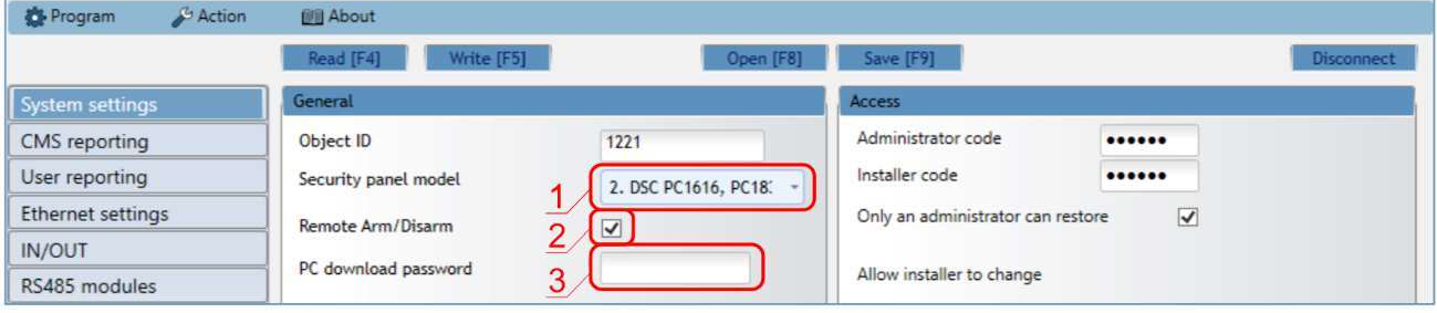
- 1 Security panel model – the type of the connected alarm control panel from the list; this determines how the communicator reads the bus.
- 2 Remote Arm/Disarm – tick it if the user wants to arm and disarm the panel from the Protegus 2 app with their own keypad code. It only appears for the directly controllable types; with the other panels, arming can be done with a keyswitch zone (section 3.4) – in that case leave it unticked.
- 3 Security panel PC download password – for Paradox and Texecom panels, the panel's PC or UDL password (4 characters); it must match the one set in the panel. The field appears after Remote Arm/Disarm is ticked.
With several panels, a setting is also needed in the panel: with Caddx, Honeywell and InnerRange panels already for reading the events (enabling the bus or the serial port), with Paradox and Texecom panels for direct control (PC or UDL password) – chapter 4 describes this make by make, together with changing the password.
2.3 Connection to the Protegus 2 app
If the user wants to see and control the system from the Protegus 2 app, set the following on the User reporting page, on the PROTEGUS Cloud tab.
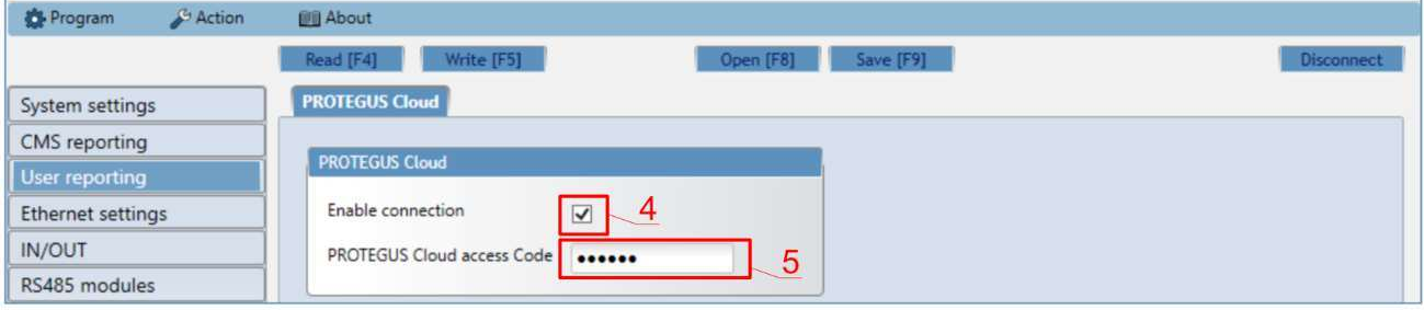
- 4 Enable connection – tick it: it enables the connection to the Protegus cloud.
- 5 Protegus Cloud access code – change the default
123456password. This is what must be entered in the app when the system is created; it cannot be changed after the system has been created.
For the network settings, Use DHCP is ticked by default on the Ethernet settings page: the device gets an IP address from the router automatically, and in most places there is nothing more to do. If there is no DHCP on the network, or a fixed address must be used, enter the manual settings here (section 6.5).
The E16 only builds outgoing connections towards the Protegus cloud and the receiver, so no port needs to be opened or forwarded on the router. On a corporate network filtered by a firewall, agree the outgoing traffic with the system administrator (section 3.2).
If the device works with Protegus 2 only, without a monitoring station, the setup is now complete: press the Write [F5] button, wait for the confirmation and unplug the USB cable. If it also reports to a monitoring station, continue with section 2.4.
2.4 Connection to the monitoring station
If the device also reports to a monitoring receiver, also enter the object ID on the System settings page.
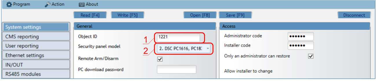
- 1 Object ID – the object ID received from the monitoring station (4 hexadecimal characters, 0–9, A–F).
FFFEandFFFFcannot be used. - 2 Security panel model – the type of the connected alarm control panel (if you have not set it in section 2.2 yet).
Then, on the CMS reporting page, in the Primary channel part, set the receiver's details.
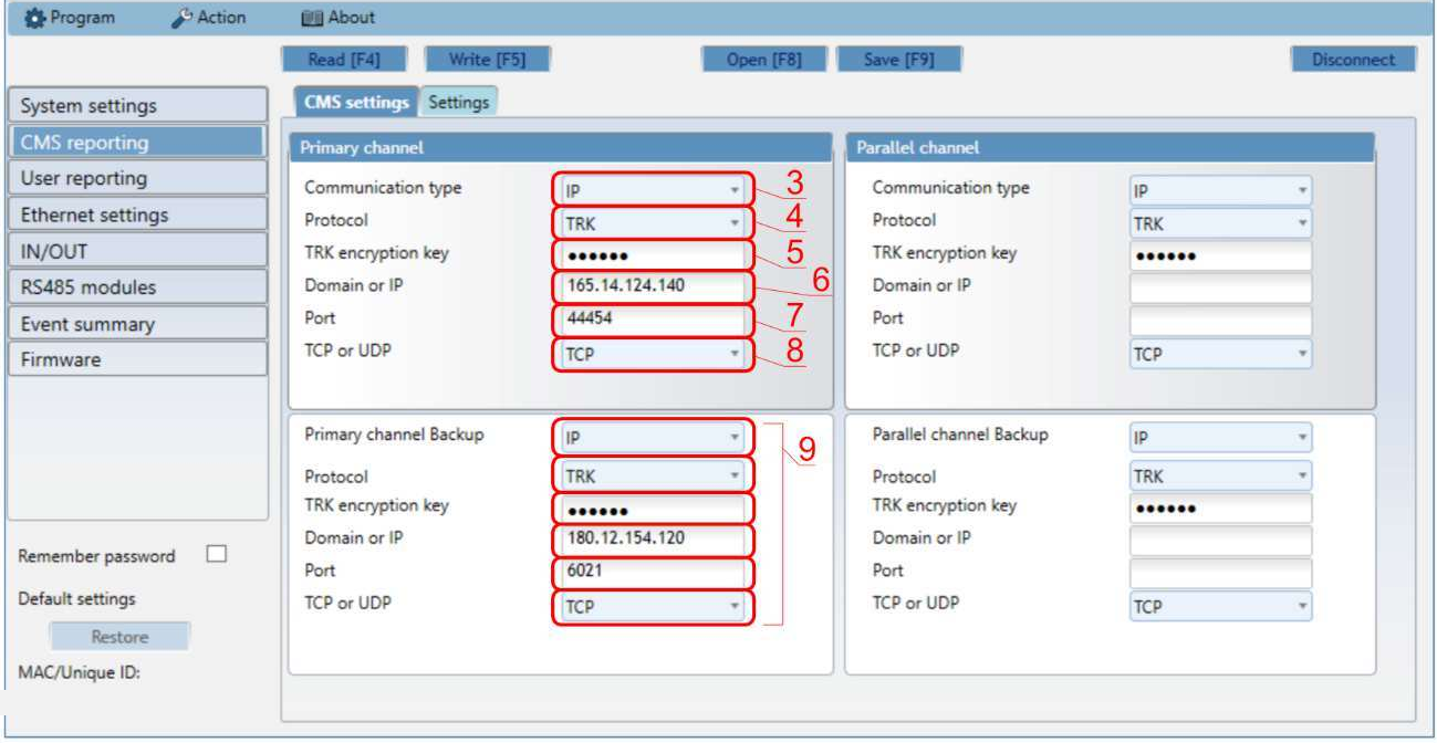
- 3 Communication type – IP (with the E16 this is the only option).
- 4 Protocol – TRK for a Trikdis receiver, DC-09_2007 or DC-09_2012 for a universal receiver, TL150 for a SUR-GARD receiver.
- 5 TRK encryption key – the 6-digit encryption key set in the receiver.
- 6 Domain or IP – the receiver's domain name or IP address.
- 7 Port – the receiver's port number.
- 8 TCP or UDP – the transmission protocol; it follows the receiver's setting.
- 9 Primary channel Backup – backup channel in case the primary fails; fill it in the same way, it is recommended.
It is also recommended to set the Parallel channel and its backup channel if the events must be received by two receivers.
With the DC-09 protocol, also enter the DC-09 object, line and receiver number on the Settings tab. If you enter the receiver with a domain name, there must be a working DNS address on the Ethernet settings page (by default Google's public name server).
At the end of the setup, press the Write [F5] button, wait for the confirmation and unplug the USB cable. The device is now ready for wiring.
3. Installation and wiring
Warining!
It is forbidden to perform wiring on a device under voltage. Before starting the work, disconnect power (including backup batteries).3.1 Installation steps
- Remove the front cover (see section 2.1) and pull off the terminal block.
- Take the printed circuit board out of the back cover: open the latch in the corner.
- Fix the back cover with screws in the chosen place.
- Put the printed circuit board back into the back cover and plug the terminal block back in.
- Plug the Ethernet cable into the RJ45 socket (section 3.8).
- Put the front cover back on.
3.2 Location and network
- Place the communicator in a dry, indoor location, preferably near the alarm control panel's enclosure, so that the bus wiring is short. A metal enclosure does not interfere: the E16 has no antenna.
- The Ethernet cable (CAT-5 or better) to the router or switch can be up to 100 m long.
- Keep the communicator and the cables away from the panel's transformer and from mains wiring.
The “up to … m” distances are theoretical maximums achievable under ideal conditions. In practice, the quality and routing of the cable, sources of interference and, for radio links, walls and terrain give a considerably shorter range. Plan with a margin, and on long runs check the connection during commissioning.
What does the network need? The communicator itself initiates the outgoing connection to the monitoring receiver and the Protegus cloud, so no port needs to be opened or forwarded on the router, and neither a public static IP address nor dynamic DNS is needed. What you do need:
- a free Ethernet port on the router or switch;
- DHCP (factory setting), or a static IP address, subnet mask, gateway and DNS provided by the network administrator;
- outgoing traffic allowed to the receiver's address and port (TCP or UDP, depending on the receiver setting), as well as to the Protegus cloud.
On a filtered – corporate or institutional – network, agree on this with the network administrator in advance: home routers allow all outgoing connections by default, but a firewall-protected network may need a separate rule.
Power cut
The E16 is powered by the alarm control panel, so during a power cut it keeps working from the panel's battery – the router and the modem, however, typically do not, and without them there is no internet. If this is not acceptable for the system, run the network devices from an uninterruptible power supply as well, or choose a cellular communicator (G16).
3.3 Connecting to the alarm control panel
The E16 connects to the panel with up to four wires (CLK is not used on the Caddx and Pyronix buses): the panel's 12 V auxiliary supply (AUX) goes to the +DC and −DC terminals, and the two data wires of the panel's keypad bus or serial port go to the CLK and DATA terminals. Which panel terminal is which differs from make to make – wire according to the diagrams below. For panels with a serial port (Paradox, Texecom), a ready-made cable is available: one end fits the panel's connector, the other end can be wired into the E16's terminal block.
The E16 can draw up to 250 mA while sending. Check that the panel's AUX output can handle this together with the other devices connected to it. Since the power comes from the panel, during a power cut the panel's battery also powers the communicator. Most panels are not damaged by swapped wires of a device connected to the bus, but swapping +DC and −DC can destroy the communicator – check the polarity before wiring.
After wiring, the type of the connected panel must be selected in the TrikdisConfig System settings → Security panel model field (section 2.2); with some makes, a setting is also needed in the panel (chapter 4).
3.3.1 DSC PowerSeries
The four Keybus terminals: RED → +DC, BLK → −DC, YEL → CLK, GRN → DATA.
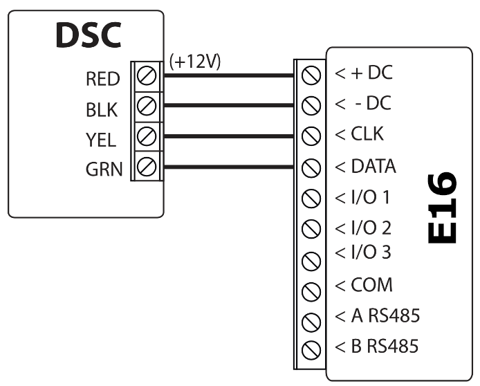
3.3.2 Paradox
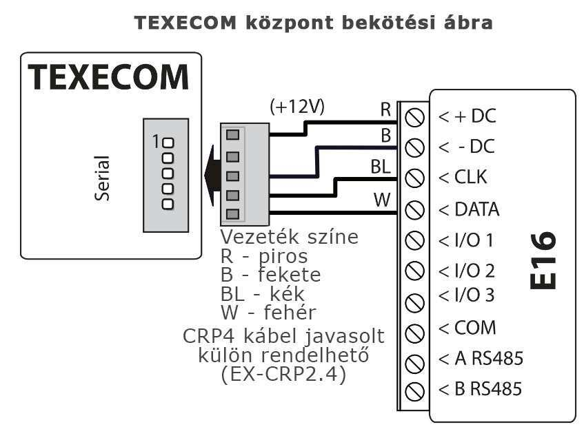
The communicator connects to the serial port (SERIAL) of Paradox panels with the ready-made CRP2 or CRP2B cable; the panel end of the cable fits the serial connector, and you wire the other end into the E16's terminal block. The 4 pins of the connector: 4 → +DC (+12 V), 3 → −DC, 2 → CLK, 1 → DATA. The wire colours of the two cables differ – the diagram shows the colour assignment of both cables. The labels of the Paradox serial connector: AUX+ (→ +DC), GND (→ −DC), Tx (→ CLK), Rx (→ DATA).
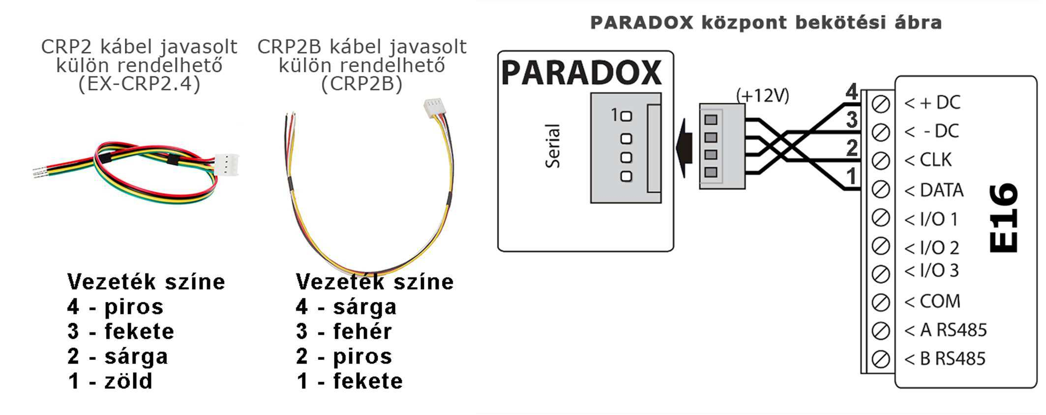
On newer Paradox panels the serial port may be locked by default – how to unlock it is described in section 4.2 and in the article Unlocking a locked serial port on Paradox alarm control panels.
3.3.3 UTC Interlogix (Caddx) NetworX
The three keypad bus terminals: POS → +DC, COM → −DC, DATA → DATA. The CLK terminal is not used.
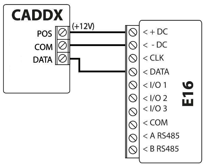
3.3.4 Texecom Premier / Premier Elite
The communicator connects to the panel's serial port with the ready-made CRP4 cable: red (R) → +DC, black (B) → −DC, blue (BL) → CLK, white (W) → DATA.
3.3.5 Crow Runner
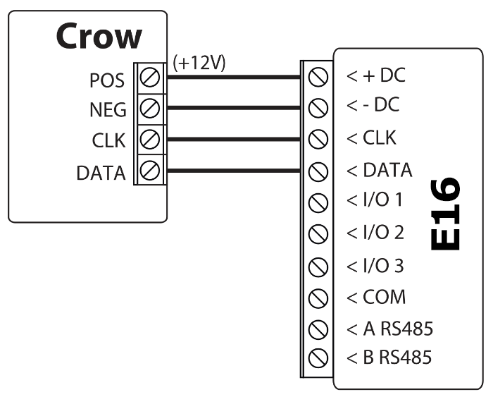
The keypad bus of the Crow Runner 4/8 and Runner 8/16: POS → +DC, NEG → −DC, CLK → CLK, DATA → DATA.
3.3.6 Pyronix
The keypad bus of Pyronix panels: +AUX → +DC, −AUX → −DC, KD → DATA. The CLK terminal is not used. After wiring and setting up the communicator, power down and restart the panel so that it accepts the communicator (section 4.5).
3.3.7 Honeywell Ademco Vista
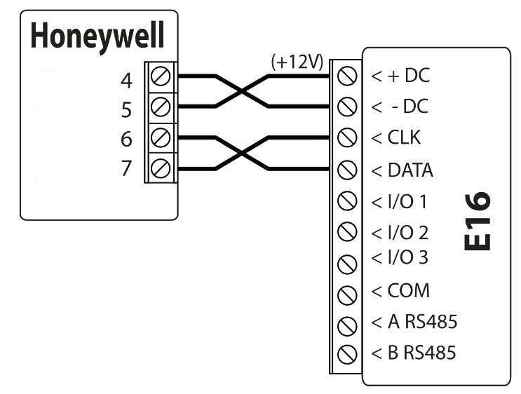
The numbered keypad bus terminals of the Vista-15, Vista-20 and Vista-48 panels: 5 (AUX +) → +DC, 4 (AUX −) → −DC, 7 (data out, yellow) → CLK, 6 (data in, green) → DATA.
3.3.8 InnerRange Inception and Integriti
With the Inception panel, the communicator gets its power from the panel's power terminals (VOUT + → +DC, 0V → −DC), and the data connection is made from the panel's USB port with the InnerRange 993030USB cable: black → 0V (−DC), green → CLK, white → DATA. Use of the serial port must be enabled in the panel (section 4.7).
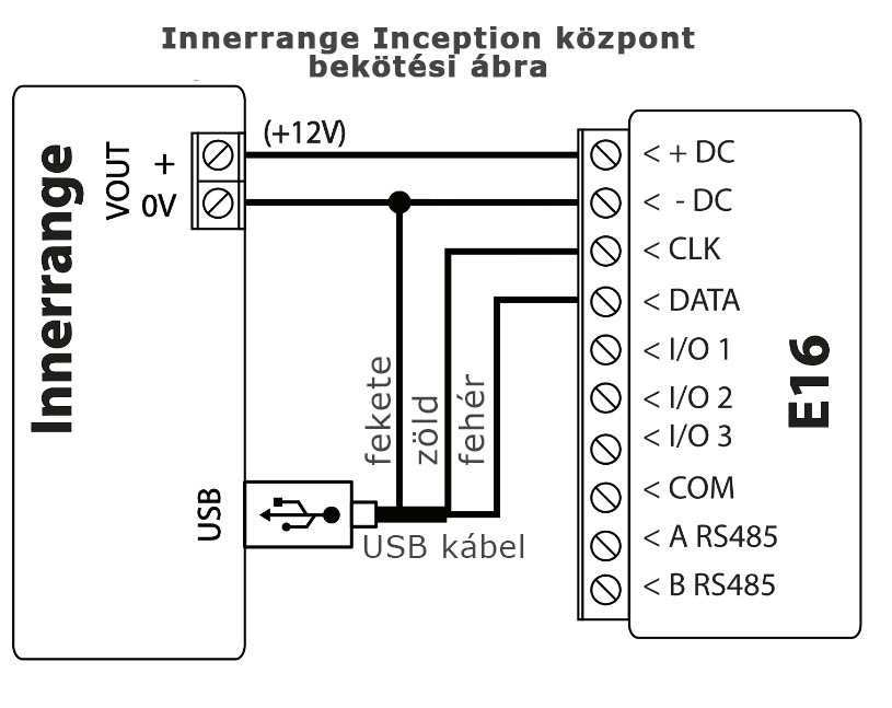
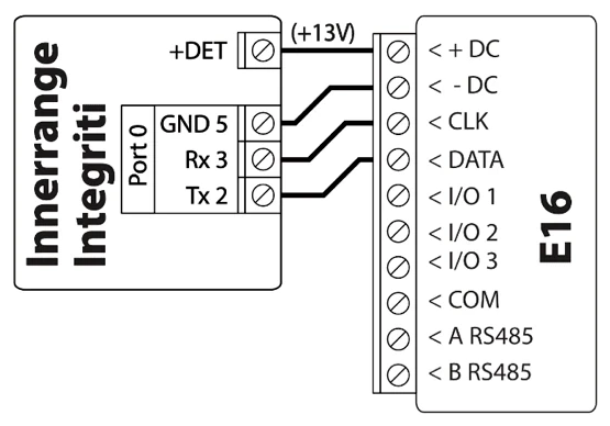
The Integriti panel's port 0 (Port 0) can be connected with the INTG-996795 cable: +DET (+13 V) → +DC, GND (5) → −DC, Rx (3) → CLK, Tx (2) → DATA. The panel's serial port must be set to the Trikdis protocol (section 4.7).
3.4 Wiring a keyswitch zone
If the panel is not one of the directly controllable types, or you do not want to use direct control, remote arming and disarming can be done with a keyswitch zone: you set one of the communicator's I/O terminals as an output (IN/OUT page, section 6.6) and connect it to a keyswitch zone of the panel. When activated, the output pulls the zone to COM (negative); wire the zone's end-of-line resistor according to the panel's zone type. Since the E16 has three I/O terminals, up to three partitions can be controlled with separate outputs.
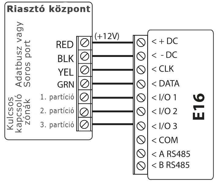
- On the TrikdisConfig System settings page, Remote Arm/Disarm must stay unticked – the two cannot be used at the same time.
- The keyswitch zone can be pulse or two-state (latching); the same mode must be set in the Protegus 2 app (section 5.3).
A separate article covers the details and pitfalls of keyswitch arming: Remote arming with a keyswitch from the Protegus 2 app.
3.5 Wiring inputs
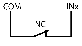
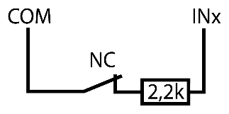
As inputs, the communicator's I/O terminals can also take additional detectors (e.g. tamper switch, panic button, temperature switch), independently of the alarm control panel. The input must be wired between the selected I/O and the COM terminal.
The inputs accept the following circuit types: NC, NO, NC/EOL, NO/EOL, NC/DEOL, NO/DEOL. The end-of-line resistor is 2.2 kΩ. With a single end-of-line resistor (EOL), both a short circuit and an open circuit count as an alarm; with double end-of-line resistors (DEOL), the two resistors allow the alarm and the tamper (short or open circuit) to be recognised separately. The factory setting is NO (normally open); you set the input type on the IN/OUT page of TrikdisConfig, according to the wiring.
| Type | Normal state | Alarm | Tamper |
|---|---|---|---|
| NC | closed | open | – |
| NO | open | closed | – |
| NC/EOL | 2.2 kΩ | open or short circuit | – |
| NO/EOL | 2.2 kΩ | short or open circuit | – |
| NC/DEOL | 2.2 kΩ | 3.3–5.5 kΩ (2 × 2.2 kΩ) | open or short circuit |
| NO/DEOL | 3.3–5.5 kΩ (2 × 2.2 kΩ) | 2.2 kΩ | open or short circuit |
When the input is triggered, the communicator sends its own event to the monitoring station and to Protegus 2; you can set the event's Contact ID code, partition and zone number on the IN/OUT page.
Wiring the input circuits: NO, NC, NC/EOL, NO/EOL, NO/DEOL and NC/DEOL types with a 2.2 kΩ end-of-line resistor; with the DEOL types the tamper circuit is also wired.

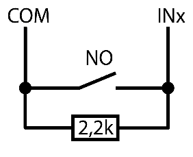

- T tamper contact ("Tamper"), signals the opening of the detector's housing

- T tamper contact ("Tamper"), signals the opening of the detector's housing
3.6 Wiring an output with a relay
As outputs, the I/O terminals are open collector (OC) outputs: in the active state they pull the connected load to negative, with up to 0.15 A, up to 30 V DC. With the relay contacts you can switch various electrical appliances on and off. Switch a larger load or a mains-voltage device through a relay: one end of the relay coil goes to +DC, the other to the I/O terminal. The I/O terminal used must be set as an output (OUT) on the TrikdisConfig IN/OUT page (section 6.6).
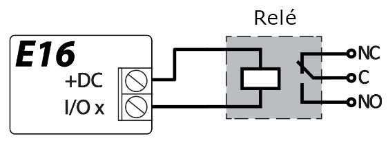
You can switch the outputs from the Protegus 2 app (chapter 5).
3.7 Wiring the iO-8 expander
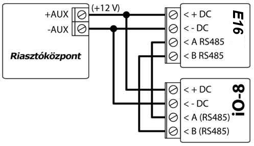
If more inputs or outputs are needed, iO-8 expanders can be connected to the E16's RS485 bus; each provides 8 more dual-function I/Os. Connect the A RS485 and B RS485 terminals to the module's A and B terminals, and take the module's power from the panel's 12 V AUX output. The module must be added on the TrikdisConfig RS485 modules page (section 6.7); the events of the inputs go to the monitoring station and to Protegus 2, and the outputs can be switched from the app.
3.8 Connecting the Ethernet cable
Plug one end of the Ethernet cable into the RJ45 socket on the E16's printed circuit board, and the other into a free port of the router or switch. A standard straight-through (patch) cable is needed; the cable enters through the opening in the case. After power-up, the green light of the NETWORK LED shows that the network connection has been established.
3.9 Power-up and first check
Starting the TRIKDIS communicator
- For SIM card communicators, insert the SIM card into the device before starting.
- For devices with Ethernet, you can connect the Ethernet cable before or after starting up.
- For startup, unplug the USB cable and connect the pulled jumper.
You can proceed to the next chapter when the device starts correctly and does not indicate any errors.
- The Power LED is green
- The Trouble LED does not flash red
- The Network LED is green (if it flashes yellow, it is okay)
- If the Data LED does not turn off, it means that the device cannot send some event. This indicates an internet / data connection error.
After wiring, the communicator starts when the alarm control panel is switched on. On the front cover you should see:
- POWER steady green – the power supply is correct;
- NETWORK steady green – connected to the network;
- TROUBLE off.
Any other LED pattern indicates some fault; identify its cause using the LED table in section 1.6. If TROUBLE is flashing, the number of flashes tells you the cause (section 1.6): 1 = no physical connection (cable, port), 2 = no IP address received (DHCP), 3 = DNS error, 6 = it cannot reach the receiver or the Protegus cloud. 7 flashes indicate that there is no connection to the panel: check the CLK and DATA wires, the selected panel type and – where needed – the panel's programming (chapter 4). If none of the LEDs is lit, check the power supply and the wiring.
4. Programming the alarm control panel
This chapter describes, make by make, what needs to be set in the alarm control panel so that the E16 reads the events and – where possible – controls the panel remotely. With most panels nothing needs to be programmed for reading the events; for direct control, tick Remote Arm/Disarm on the TrikdisConfig System settings page, and for Paradox and Texecom panels also enter the panel's PC or UDL password in the Security panel PC download password field (sections 2.2 and 6.2).
If you control the panel not directly but through a keyswitch zone (section 3.4), Remote Arm/Disarm must stay unticked, and this chapter only applies to the settings needed for reading the events.
4.1 DSC
DSC PowerSeries panels (the list of supported models is in section 1.2) do not require any special settings: the communicator connected to the Keybus reads the events immediately, and once Remote Arm/Disarm is ticked, the user arms and disarms from the app with their own keypad code. The details of direct control – zone states, zone bypassing, automatic detection of partitions – are covered in a separate article: Direct control for DSC PowerSeries alarm panels.
The communicator does not work with DSC PowerSeries NEO panels: the manufacturer does not allow external devices on the NEO bus. For NEO, use a telephone-line (TIP/RING) communicator – see DSC Power Series NEO and Trikdis communicators: compatibility and solutions.
4.2 Paradox
Paradox panels only need to be programmed for direct control; nothing needs to be set for reading the events. The panel's firmware must be at least V.4.
On newer Paradox panels (for example the SP+, MG+ and EVOHD+ series), the serial port may be locked from the factory: the communicator receives no data until the port is unlocked. How to unlock it: Unlocking the locked serial port on Paradox alarm panels.
For control, the panel's PC password must be set, and the same must be entered in the System settings → Security panel PC download password field of TrikdisConfig – the two must match.
- Enter the panel's installer programming on the keypad.
- Open the PC password section: section 911 for the MAGELLAN and SPECTRA series, section 3012 for the DIGIPLEX EVO series.
- Enter a 4-character password. The password cannot be 0000 and must not start with zero.
- Exit programming and restart the panel – a change of the PC password takes effect after a restart. Then enter the same password in TrikdisConfig.
Typical problems and their solutions
- The keypad code assigned to the partition cannot be the master code: give the user another code, and with that, arming / disarming from Protegus 2 will work.
- Restart the communicator after any keypad code change (power cycle or
RESETSMS command): it reads the codes at start-up and does not see later changes.
4.3 Texecom
Texecom Premier / Premier Elite panels must be programmed both for reading events and for control: you need to set the panel's 4-character password called UDL passcode, and enter the same in the System settings → Security panel PC download password field of TrikdisConfig – the two must match.
With Texecom's Wintex software: the UDL passcode is on the Options tab of the Communication Options window.
From the keypad:
- Enter the 4-digit installer code and press [Menu] to enter the programming menu.
- Immediately afterwards, press [9].
- Press [7][6], then [2], and enter the 4-digit UDL passcode.
- Press [Yes], then exit programming with the [Menu] button.
4.4 UTC Interlogix (Caddx)
The firmware of the UTC Interlogix (Caddx) NetworX panel must be at least V2. The following must be set on the panel's keypad:
- Press [*][8] and enter the installer code (default 9713).
- Enter the device number (device address) assigned to the communicator (default 0).
- Program the rows of the table below one after the other: enter the location, the segment number and then the setting. You can go back to the previous field with the [*] button.
12345678means that all eight switches of the segment are on (all digits are visible on the display).
| Location | Segment | Setting |
|---|---|---|
| 23 | 3 | 12345678 |
| 37 (not strictly necessary) | 3 | 12345678 |
| 37 (not strictly necessary) | 4 | 1234567* |
| 90 | 3 | 12345678 |
| 93 | 3 | 12345678 |
| 96 | 3 | 12345678 |
| 99 | 3 | 12345678 |
| 102 | 3 | 12345678 |
| 105 | 3 | 12345678 |
| 108 | 3 | 12345678 |
- When you have programmed all rows, press [Exit] twice to leave programming.
4.5 Crow and Pyronix
The Crow Runner 4/8 and Runner 8/16 panels do not require any special settings.
Pyronix panels do not require programming either, but after setting up and wiring the communicator, power down the panel completely (mains and battery) and restart it: the panel accepts the communicator connected to its bus at start-up.
4.6 Honeywell Ademco Vista
The firmware of the Honeywell Ademco Vista-20 and Vista-48 panels must be at least V5.3. The settings are made on the panel's keypad.
Entering programming – in two ways:
- enter the installer code (default 4112), then press [8][0][0]; or
- power up the panel and within 50 seconds press the [*] and [#] buttons at the same time (this only works if programming was previously exited with [*][9][8]).
Settings:
- Enable sending Contact ID events on the long range radio (LRR) output: press [*][2][9][1][#].
- For remote control, enable the use of the 2nd AUI address: press [*][1][8][9][1][1][#].
Exiting programming: press [*][9][9].
4.7 InnerRange Inception and Integriti
The firmware of the InnerRange Inception panel must be at least 2.3.0.3507-r0, and the panel needs an internet connection. The settings are made in the panel's web interface:
- Open
https://skytunnel.com.au/inception/SERIALNUMBERin a browser, where SERIALNUMBER is the serial number on the panel's box. Log in with the installer account. - Open the Configuration → General → Alarm Reporting page.
- In the 3rd Party Device Configuration group: - tick Enable 3rd Party Device Reporting; - in the 3rd Party Device Type field, select Trikdis; - in the Serial Port field, select Serial Port 1 (Plugged In, In Use By 3rd Party Device).
- Save the settings and log out of the interface.
The firmware of the InnerRange Integriti panel must be at least 19.1.0.36608, and its programming software (Integriti Professional) at least 19.1.0.15396. The settings are made in the panel's programming software:
- For the serial port (TTL Port-0) to which the communicator is connected, select the Trikdis communication protocol.
- The data format must be Contact ID.
- Port settings: 19200, 8, N, 1.
- Save the settings and exit the program.
The Inception and the Integriti pass the events to the communicator; arming and disarming requires a keyswitch zone (sections 1.2 and 3.4).
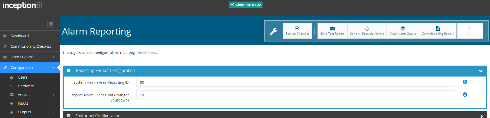

- 1 Enable 3rd Party Device Reporting – ticked.
- 2 3rd Party Device Type – Trikdis.
- 3 Serial Port – Serial Port 1 (Plugged In, In Use By 3rd Party Device).
5. Remote control with the Protegus 2 app
With the Protegus 2 mobile and web app, the user sees the status of the system remotely, receives notifications about events, can arm and disarm, and can switch the communicator's outputs. With the E16, arming can be done in two ways: with the directly controllable panels the user uses their own keypad code, with panels wired with a keyswitch zone the communicator's output is used.
5.1 Adding the device
Before adding the device, check:
- The E16 is connected to the network and reaches the internet: the NETWORK LED is steady green, the TROUBLE LED is not flashing.
- On the TrikdisConfig User reporting → PROTEGUS Cloud tab, Enable connection is ticked and the Protegus Cloud access code is set (it cannot be changed after the system has been created).
- The POWER LED is steady green.
Creating the system in the Protegus 2 application
- Download the Protegus 2 application to your phone or open it in a browser
- Register an account if you haven't already.
- Log into your account.
- On the main page, click the "+" button to create a system
- Enter the unique identifier of the TRIKDIS device (you can also scan the barcode or QR code with your phone's camera), which you can find
- On the sticker of the device
- On the device's cardboard box
- In the bottom left corner of TrikdisConfig (selectable and copyable format)
- Enter the system name and select a time zone
- Your system is created, you can still name the partitions and zones at the next step, but you can do this later anytime.
- In the last step, your system's home screen will appear. Wait until the yellow stripe disappears and your system is ready.


With the E16, the device's unique identifier is the MAC address (Unique ID): it can be read on the box and on the back cover of the device, and the TrikdisConfig status bar also shows it (section 6.1). In the app, this is what must be entered as the device identifier when the system is created.
5.2 Direct control with the keypad code
If the panel is one of the directly controllable types (section 1.2) and Remote Arm/Disarm is ticked on the TrikdisConfig System settings page, Protegus 2 shows the panel's partitions with the status read from the bus, and for arming / disarming the user enters the panel's keypad code in the app – the same one they use on the keypad. No separate output or keyswitch zone is needed.
- Depending on the make, this requires a setting in the panel (Paradox: PC password, Texecom: UDL password; with Caddx, Honeywell and InnerRange panels, enabling the bus or the serial port is needed already for reading the events) – see chapter 4.
- The keypad code is checked by the panel, and the panel's event log also records the user, not the communicator.
- With a Paradox panel, the user's code cannot be the master code; after changing the code, restart the communicator (section 4.2).
- With a DSC PowerSeries panel, the app also shows the status of the zones, and zone bypassing is also possible – details in the article on DSC direct control (the article is about the G16, but it applies to the E16 in the same way).
When the system is created, Protegus 2 asks whether arming is controlled by the communicator's output. With direct control, do not assign an output to the partition (Control with Protegus2 switched off): the partition is handled by the panel, and the status comes from the bus.
5.3 Arming with a keyswitch zone
If the panel cannot be controlled directly, or you do not want to use it that way, you connect one of the communicator's outputs to the panel's keyswitch zone (section 3.4), Remote Arm/Disarm stays unticked in TrikdisConfig, and in Protegus 2 you assign the output to the partition.
If you want to arm and disarm the alarm panel with the communicator's output, through the panel's keyswitch zone, specify in the Protegus 2 app for the partition which output controls it.
The panel zone to which the communicator's output is connected must be programmed as a keyswitch zone in the panel, and the panel must report the arming and disarming events – Protegus 2 shows the partition state based on these.
You can make the setting when creating the system, while adding the partitions, or later in the system settings, when editing the partition. When creating the system, the Protegus 2 wizard guides you through: click Continue, enter the partition name (Area name) and enable control of the PGM output from the Protegus 2 app – this is done with the following steps:
- Select (or add) the partition you want to control. The partition number must match the one the panel sends in its events (partition 1 as 1, partition 2 as 2).
- Switch on Control with Protegus2 (control with PGM), and in the Assigned Output field select the communicator output (PGM1, PGM2 …). One output can control only one partition.
- Select the operating mode: Pulse or Level (latched) – the same one you set for the keyswitch zone in the panel. Typically we use pulse; the pulse length can also be set (default 3 s).
- Save the setting (Save). With several partitions, repeat this for each one with its own output: in the wizard you add a further partition with the Click to add an area button and set its PGM output in the same way. When you have set up all partitions, move on in the wizard with the Skip button.
Protegus 2 can only show the state of the partitions correctly if the panel sends the arming and disarming events with the correct partition number. The details and pitfalls of keyswitch arming are covered in a separate article: Remote arming with a keyswitch from the Protegus 2 app.
5.4 Arming and disarming from the app
- Open the system in the Protegus 2 app. On the home screen every partition has its own card and padlock: a closed, red padlock means an armed partition, an open, green padlock a disarmed one.
- Tap the partition's padlock and select the required action: arm or disarm.
- If the app asks for it, enter the PIN code.
The padlock takes on the actual state in response to the event received from the alarm panel; the app also confirms in the event list and in a notification whether the panel has carried out the action.
With direct control, the app asks for the panel's keypad code; with keyswitch arming – if it is switched on – for the Protegus 2 password.
The E16 has no SMS control and no SMS notifications: arming, disarming and switching the outputs are done from the Protegus 2 app, and notifications arrive as push messages.
6. TrikdisConfig – the settings in detail
On the left side of the TrikdisConfig window you see the list of pages (System settings, CMS reporting, User reporting, Ethernet settings, IN/OUT, RS485 modules, Event summary, Firmware), at the top the button bar (Read [F4], Write [F5], Open [F8], Save [F9]), and at the bottom the status bar. This chapter goes through the E16's settings page by page.
6.1 The status bar
After connecting the device and reading it (Read [F4]), the most important device data are shown at the bottom of the window:
| Label | Meaning |
|---|---|
| IMEI / Unique ID, on an Ethernet device MAC / Unique ID | The device's unique identifier: the IMEI on a device with a SIM card, the MAC address on an Ethernet device. The same is printed on the box and on the back of the device. |
| Status | The current operating status. |
| Device | The device type (model designation). Check that the type of your own device is shown here. |
| SN | Serial number. |
| BL | The bootloader version. |
| FW | The firmware version. |
| HW | The hardware version. |
| State | The connection mode: USB or remote. |
| Administrator / Installer | The access level of the person programming (after the password has been entered). |
After making the settings, you write them to the device with the Write [F5] button; with the Open [F8] and Save [F9] buttons you can save the complete set of settings to a file and load it into another device. Save [F9] saves the settings to a settings file, and Open [F8] opens the saved file; you can later load the saved settings into other devices as well, so you can quickly set up several devices with identical settings.

With the E16, the device's unique identifier is the MAC address: this is what Protegus 2 asks for when the system is created, and what TrikdisConfig asks for for remote access (Unique ID). The same address can also be read on the box and on the back cover of the device.
6.2 System settings
The page consists of two groups: in the General group you set the device's basic operation and its connection to the alarm control panel, in the Access group the access levels.
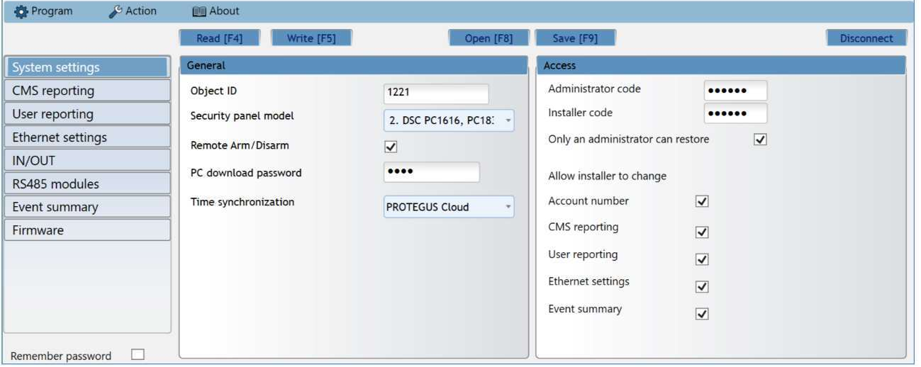
- Object ID – the object ID received from the monitoring station (4 hexadecimal characters, 0–9, A–F). Mandatory if the device also reports to a monitoring station;
FFFEandFFFFcannot be used. - Security panel model – the type of the connected alarm control panel from the list. This determines how the communicator reads the bus, so choose the exact type of the connected panel.
- Remote Arm/Disarm – when ticked, the communicator controls the panel directly: the user arms and disarms from Protegus 2 with their keypad code. It only appears for the directly controllable panel types; depending on the make, it requires a setting in the panel (chapter 4). With keyswitch-zone arming, leave it unticked.
- Security panel PC download password – for direct control of a Paradox or Texecom panel, the panel's PC or UDL password (4 characters); it must match the one set in the panel (sections 4.2 and 4.3).
- Time synchronization – the source of the device's clock (default PROTEGUS Cloud, the Protegus cloud).
In the Access group you manage the access levels and passwords.
There are two access levels for the device settings: administrator and installer.
- Administrator code – access to all settings (default password:
123456; the password is 6 characters: digits or Latin letters). - Installer code – access that can be restricted (default password:
654321). - Only an administrator can restore – when ticked, only the administrator can start restoring the factory settings.
- Allow installer to change – here you can select which groups of settings the installer may change: Account number, CMS reporting, User reporting, SIM card (on a mobile network device) or Ethernet settings (on an Ethernet device), Event summary.
Do not leave the default passwords in the device!
During commissioning, change at least the administrator password and note it down in a safe place. If the password is forgotten, the only remedy is restoring the factory settings, which deletes all settings.
6.3 CMS reporting
The communicator sends the events to the monitoring station over an IP connection. The events can go over several channels: the primary and the parallel channel work at the same time (to two receivers at once), and each has a backup channel that takes over if the given channel is interrupted. The communication is encrypted and password-protected; for receiving and forwarding to the monitoring software, a Trikdis receiver (IPcom software receiver for Windows or Linux, RL14 hardware IP/SMS receiver, RM14 multi-channel receiver) or a universal receiver that supports the DC-09 / TL150 protocol is needed.
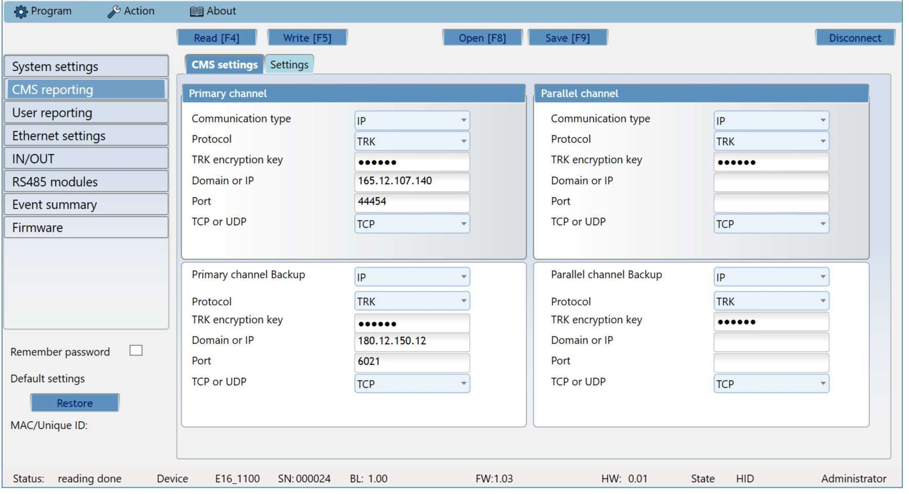
Primary channel
- Communication type – IP; with the Disable value the channel can be switched off (for example if the device works with Protegus 2 only, without a monitoring station).
- Protocol – TRK (Trikdis receivers), DC-09_2007 or DC-09_2012 (universal receivers), TL150 (SUR-GARD).
- TRK encryption key – 6-digit encryption key; it must be the same in the communicator and in the receiver.
- Domain or IP, Port – the receiver's address and port.
- TCP or UDP – the transmission protocol.
Primary channel Backup – backup channel. It takes over the communication if the primary channel does not work; its settings are the same as above. Since the E16 communicates over a single network path (the local network), the backup channel is a second receiver address on the same path: it bridges a fault on the receiver side, but not a loss of the internet connection.
Parallel channel. Alongside the primary, it sends to a second receiver at the same time (for example to the local and the central monitoring station). It has its own backup channel.
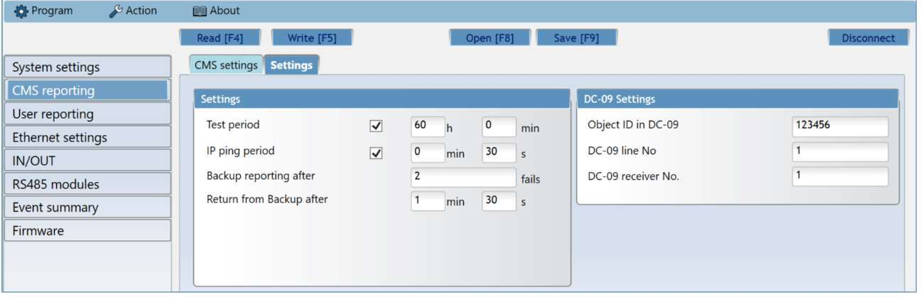
On the Settings tab you set the timings and the DC-09 data.
- Test period – the interval of the periodic test report (default 24 hours). The test report is sent as a Contact ID message to the monitoring station and to Protegus 2.
- IP ping period – the interval of the keep-alive signal (PING) on the IP channel (default 30 s). You enable it with the tick box and enter the time in the minutes (min) and seconds (s) fields; it is required for connection supervision. The receiver does not forward PINGs to the monitoring software so as not to overload it; the software only receives a message if the receiver gets no PING for three times the set period. For example, if the PING period is 3 minutes, the loss of connection is reported after the 9th minute.
- Backup reporting after – after this many failed sending attempts the device switches to the backup channel (default 2).
- Return from Backup after – after this time it returns to the primary channel (default 1 min 30 s).
The PING keeps the live connection between the device and the receiver, and remote access, control and programming also depend on it. That is why we do not recommend a PING period longer than 5 minutes.
DC-09 Settings (on the right side of the tab) – only needs to be filled in if you send with the DC-09_2007 or DC-09_2012 protocol on any channel; the group appears when DC-09_2007 or DC-09_2012 is selected in the Protocol field of any channel:
- Object ID in DC-09 – a 3–16 character hexadecimal identifier, provided by the monitoring station.
- DC-09 line No – the line number.
- DC-09 receiver No. – the receiver number.
The DC-09 settings group is only visible if the DC-09 protocol is set on one of the channels. With the E16, you enter the name servers (DNS) not here but on the Ethernet settings page (section 6.5).
6.4 User reporting
On the PROTEGUS Cloud tab you enable the Protegus service, with which the user can monitor and control the communicator remotely; more about the service: www.protegus.app. The E16 has no SMS notifications and no SMS control, so this page only has this one tab.
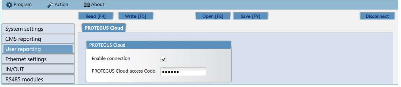
- Enable connection – enables the connection to the Protegus cloud and remote access with TrikdisConfig.
- Protegus Cloud access code – 6-digit code for the Protegus connection (default
123456). It can only be set before the system is created in Protegus 2; it cannot be changed afterwards.
6.5 Ethernet settings
Here you set how the E16 connects to the local network. By default Use DHCP is ticked: the device gets its address, gateway and name servers from the router automatically, and in most places there is nothing to do.

- Use DHCP – when ticked, the device automatically gets its IP address, subnet mask and gateway from the router's DHCP server. This is the factory setting, and in most places nothing more needs to be done. If there is no DHCP on the network, if automatic login to the network fails, or if the network administrator asks for a static address, untick it and fill in the fields below and the name servers manually:
- Static IP – the device's static IP address on the local network (an address not used by any other device and outside the DHCP range).
- Subnet mask – the subnet mask of the network.
- Default gateway – the default gateway, usually the router's address. With a wrong gateway the device reaches the local network but not the internet.
- DNS 1, DNS 2 – name servers; through these the device finds the Protegus cloud and a receiver specified by domain name. Google's public DNS is set by default; if the network only allows its own name server towards the outside, enter the address of the local DNS here. 3 flashes of the TROUBLE LED indicate a DNS error.
The device's unique identifier, the MAC address (Internal MAC in the software), is shown in the newer TrikdisConfig window not on this page but at the bottom of the window, in the MAC / Unique ID field of the status bar.
The device only builds outgoing connections to the receiver and the Protegus cloud, so no port needs to be opened or forwarded on the router, and no public static IP address is needed either.
6.6 IN/OUT
Here you specify the role of the communicator's three dual-function I/O terminals: Disabled (not used), IN (input) or OUT (output). For an input, the type must also be specified (NC, NO, NO/EOL, NC/EOL, NO/DEOL, NC/DEOL). Default setting: I/O 1 and I/O 2 inputs (NO), I/O 3 output.
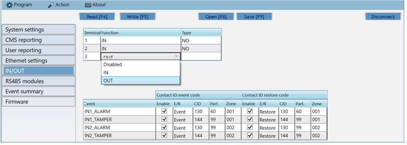
When the detector connected to the input is violated, the communicator sends its own event (INx_ALARM, Contact ID 130), and when the tamper circuit is violated, a tamper event (INx_TAMPER, 144), to the monitoring station and to Protegus 2; the events of every terminal set as an input appear in the table. The columns of the table:
- Enable – enables sending the message.
- E/R – the event type: Event (alarm) or Restore.
- CID – the Contact ID code; you can enter it or keep the default value. The event goes to Protegus 2 and to the monitoring station with this code.
- Part. – the partition number in the message.
- Zone – the zone number in the message.
6.7 RS485 modules
The iO-8 expanders connected to the RS485 bus must be added on the Modules list tab.

- Module Type – the type of the connected module from the list (Expander iO-8).
- Serial No – the module's 6-digit serial number (on the module and its box, SN).
After selecting the module and entering the serial number, press the Write [F5] button, unplug the USB cable and wait a minute while the communicator registers the module. Then plug the cable back in, read the device (Read [F4]), and the module's own numbered tab appears on the RS485 modules page.
iO-8 expander – 8 dual-function I/Os; up to 4 modules can be connected to the communicator.
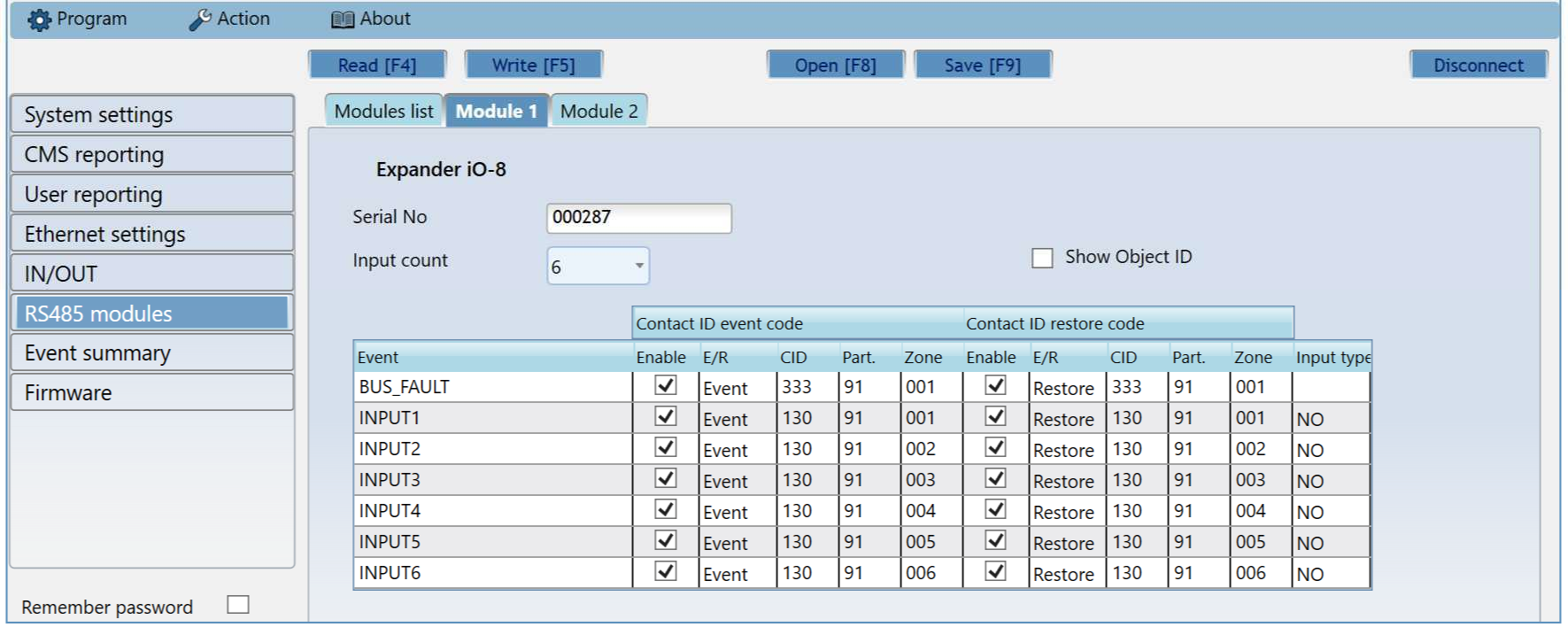
- Input Count – how many terminals should be inputs; the rest will be outputs. The input type (Input type: NO or NC) can be set in the table. You set the role of the outputs (arming / disarming with a keyswitch zone or switching a device) in the Protegus 2 app.
- In the table you can assign Contact ID codes to the bus fault (BUS_FAULT, Contact ID 333) and to the alarm and restore events of the inputs (INPUTx, 130) (Enable, E/R, CID, Part., Zone). By default, module 1 reports with partition 91 and module 4 with partition 94. By ticking Show Object ID, an object ID different from the communicator's can also be given for the inputs.
6.8 Event summary
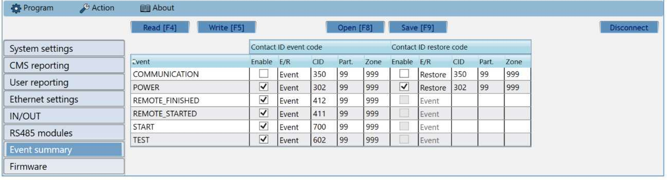
On this page you can enable or disable the device's own internal messages and change their Contact ID code, partition and zone number. A message disabled here is not sent by the device on any channel. By default the messages are sent with partition 99 and zone 999.
| Message | Contact ID | When it is generated |
|---|---|---|
| COMMUNICATION | 350 | Communication between the communicator and the alarm panel has been lost (disabled by default). A communicator connected to the bus or serial port detects this directly; a telephone-line communicator only with Line supervision enabled. |
| POWER | 302 | Inadequate (low) supply voltage; its restore is a separate message. |
| REMOTE_STARTED | 411 | Remote programming with TrikdisConfig has started. |
| REMOTE_FINISHED | 412 | Remote programming has finished. |
| START | 700 | The device has connected to the network (start-up). |
| TEST | 602 | Periodic test report. |
| PING | 760 | The PING keep-alive message. It is not in every device's list: it appears on the screen of the earlier hardware version, while the Event summary page of the newer versions has no such row. Its interval is set in the CMS reporting → Settings → IP ping period field. |
- Enable – enables sending the message to the monitoring station and to Protegus 2.
- E/R – the message type: Event or Restore – the row stands for the occurrence of the event or its restore.
- Part. – the partition (area) number the device sends with the internal event and its restore.
- Zone – the zone number the device sends with the internal event and its restore.
- The CID code, the partition and the zone can be changed for any event; where there is a restore (Restore), its code can be set separately.
The events of the device's own inputs (INx_ALARM, INx_TAMPER) are set on the IN/OUT page, and the events of the expansion modules (BUS_FAULT, INPUTx) on the RS485 modules page, on the module's tab. Enabling the test report and its interval are set in the CMS reporting → Settings → Test period field.
6.9 Restoring the factory settings
To restore the factory settings, click the Restore button in the Default settings group at the bottom left of the TrikdisConfig window. Restoring deletes all settings – including the passwords – so it is worth saving the settings to a file first (Save [F9]).
With the installer password this is only possible if the administrator has not disabled it on the System settings → Access page.
7. Remote programming
TrikdisConfig reaches Trikdis devices not only over a USB cable but also remotely, via the Protegus cloud. This way you can change the settings of an already installed device without going to the site.
Remote access requires:
- The device must be switched on and have a network connection (the POWER and NETWORK LEDs are lit green; on a mobile network device the NETWORK LED also flashes yellow). On a mobile network device, the inserted SIM card must be active and its PIN code must be entered in the device, or the PIN request must be disabled; on an Ethernet device, the network (LAN) cable must be plugged in and the device must be able to reach the internet.
- On the User reporting → PROTEGUS Cloud page of TrikdisConfig, Enable connection must be ticked (set this over USB during the first commissioning).
- You need to know the device's unique identifier (IMEI or MAC – printed on the box and on the back of the device) and the administrator or installer password.
Steps:
- Start the TrikdisConfig software.
- In the Remote access section, enter the device's unique identifier (IMEI or MAC) in the Unique ID field.
- Optionally, give the system a name in the System name field – the software remembers it, and next time you can choose it from the drop-down list.
- Press the Configure button.
- In the window that opens, click the Read [F4] button and enter the password. With the Remember password tick box, the software remembers it for this session.
- Make the changes, then send them to the device with the Write [F5] button.
The software saves the named systems you have programmed remotely before; you can list them with the arrow next to the System name field. To delete one, select the identifier in the list, press the Delete key and confirm.

8. Testing the communicator
After programming and wiring, always check the whole chain: alarm panel → communicator → monitoring station and/or Protegus 2.
Before that, check that there is power (the POWER LED is lit green) and a network connection (the NETWORK LED is lit green).
- Trigger an event. Arm and then disarm the system on the keypad, or violate a zone while the system is armed so that an alarm is generated.
- Check that it arrives. See whether the event has appeared in the monitoring software and/or in the event list of the Protegus 2 app – with the correct partition and zone number.
- Inputs. Trigger the detector wired to the communicator's own input and check the corresponding event.
- Outputs. Switch the output from the Protegus 2 app and check that the connected device (relay, keyswitch zone) actually operates.
- Remote arming. If the panel can be controlled remotely, also arm and disarm it from the Protegus 2 app.
With a panel connected to the bus, also check that the communicator really reads from the panel: arm and disarm the panel on the keypad, and check that the event appears in the Protegus 2 event list (and at the monitoring station) with the correct partition and user number. With direct control, also do a test arming from the app, with the user's keypad code.
Also check the network fallback: unplug the Ethernet cable and check that the TROUBLE LED signals the loss with 1 flash, then, after plugging it back in, that the NETWORK LED is steady green again and the stored events arrive at the monitoring station and in the app.
9. Firmware update
You can update the firmware yourself – to a newer version and, if necessary, to an older one as well. All device settings remain unchanged after the update.
- Start the TrikdisConfig software and connect the device with a USB cable, or open its programming remotely.
- If newer firmware is available, the software offers to download it – accept it.
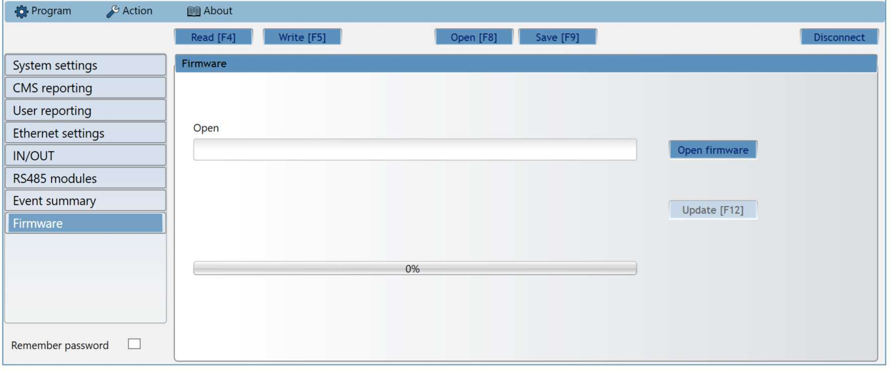
- Select the Firmware page and click the Open firmware button. Select the firmware file.
- Press the Update [F12] button, wait for the update to finish, then click OK in the pop-up window. Do not unplug the cable or interrupt the connection in the meantime.
The firmware files are in the TrikdisConfig installation folder, inside the Firmwares subfolder, in the folder named after the device. If there is no such folder, either there is no update for it or the TrikdisConfig software itself needs to be updated. The latest files can also be downloaded as a registered user from the device's page on the manufacturer's website.
The update requires an internet connection. An antivirus program, a firewall or strict network settings can prevent the automatic firmware download; in that case change the antivirus settings, or download the file manually and open it on the Firmware page.
10. Troubleshooting and frequently asked questions
The most common questions and faults, starting from the LED indications. Where the answer refers to a detailed chapter, you will find the exact place of the setting there.
The NETWORK LED is off – no network
- Look at the flashes of the TROUBLE LED: 1 = no physical connection (cable, port), 2 = no IP address received (DHCP), 3 = it cannot resolve the name of the receiver or the Protegus cloud (DNS).
- 1 flash: check the Ethernet cable at both ends, and whether the router or switch port is live (the port LED is lit); try another port or cable.
- 2 flashes: DHCP must be switched on in the router, or give the device a fixed IP address on the Ethernet settings page (section 6.5). On a corporate network, the system administrator can allow the device based on its MAC address.
- 3 flashes: the name server cannot be reached. By default Google's public DNS is set; if the network blocks external DNS, enter the local name server on the Ethernet settings page.
There is a network, but the monitoring station receives no events
The DATA LED is the simplest internet check. The DATA LED is lit when there is a message waiting to be sent in the device's memory. A green NETWORK LED only tells you that the network connection has been established – for a mobile network device, that it has registered on the operator's network; for an Ethernet device, that the connection up to the router is alive – but not that the device can also reach the internet. If the NETWORK LED is green but the DATA LED stays lit continuously even after an event or test report, the internet connection is not working: the message cannot be sent. On a mobile network the most common culprit is the APN or the data service of the SIM card; on Ethernet, the router, the firewall or the DNS. When the DATA LED goes out, the message has been sent and the data connection is fine.
- 6 flashes of the TROUBLE LED indicate that there is no connection to the receiver: check the receiver's address, port, the TCP/UDP setting and the encryption key (CMS reporting).
- If the receiver is entered with a domain name, check the DNS setting (Ethernet settings).
- On a network filtered by a firewall, outgoing TCP/UDP traffic to the receiver's port must be allowed; no port needs to be opened (inbound) on the router.
The TROUBLE LED flashes seven times – the communicator does not see the panel
- Check the wiring according to the diagram in section 3.3: the most common mistake is swapped CLK and DATA wires, or a data line connected to the wrong panel terminal.
- The exact type of the connected panel must be selected in the TrikdisConfig System settings → Security panel model field.
- With Texecom, Caddx, Honeywell and InnerRange panels, a setting is also needed in the panel (chapter 4) – without it the panel does not put data on the bus.
- With a Paradox panel, the serial port may be locked by default – here is how to unlock it.
- After wiring, power down and restart a Pyronix panel so that it accepts the communicator.
- The E16 does not work with a DSC PowerSeries NEO panel (it does not allow external devices on the NEO bus) – a telephone line communicator (E16T) is needed here.
The events arrive, but I cannot arm from the app
With direct control:
- Remote Arm/Disarm must be ticked on the System settings page.
- With Paradox and Texecom panels, the Security panel PC download password must match the panel's PC or UDL password (sections 4.2 and 4.3).
- With a Paradox panel, the panel's firmware must be at least V.4; the user's code must not be the master code; after changing the code, restart the communicator.
- With a Honeywell Vista panel, the 2nd AUI address must be enabled (section 4.6).
- In Protegus 2, no output may be assigned to the partition (Control with Protegus2 switched off).
With a keyswitch zone:
- Remote Arm/Disarm must be unticked, and the I/O terminal must be OUT on the IN/OUT page.
- The panel's zone must be of the keyswitch type, and in Protegus 2 the right output must be assigned to the partition, in the pulse or two-state (latching) mode matching the zone (section 5.3).
Protegus 2 does not see the device
- Enable connection must be ticked on the User reporting → PROTEGUS Cloud tab.
- When the system is created, the Protegus Cloud access code set in the device must be entered; it cannot be changed in the device after the system has been created.
- Enter the MAC address (Unique ID) exactly, from the box or the back cover.
- The device must be online: the NETWORK LED is green, TROUBLE is not flashing, and the DATA LED goes off after an event. On a network with a firewall, the outgoing connection towards the Protegus cloud must be allowed.
I cannot log in remotely with TrikdisConfig
- The device must be online (NETWORK LED green), and the Protegus connection must be enabled.
- CMS reporting → Settings → IP ping period must not be longer than 5 minutes: the PING keeps up the connection needed for remote access.
- Check the administrator or installer password.
I have forgotten the password
Only restoring the factory settings helps (section 6.9); this requires a USB connection, and all settings are deleted. If the administrator has disabled the installer reset, the reset cannot be started without the administrator password either.
Do I need to open or forward a port on the router?
No. The E16 only builds outgoing connections towards the receiver and the Protegus cloud, so neither port forwarding nor a public IP address is needed; remote programming also goes through this outgoing connection. Just make sure that the firewall does not block outgoing traffic to the receiver's port and towards the Protegus cloud.
Does it work over Wi-Fi or a mobile network?
No: the E16 only has a wired Ethernet connector. If the router does not have a reliable power supply, run the network devices from an uninterruptible power supply.
What happens during a power cut?
The E16 is powered by the alarm control panel, so it keeps working from the panel's battery, but the router and the modem typically stop, and with that the internet is gone. While there is no connection, the TROUBLE LED signals with 1 or 6 flashes, the device stores the events (up to 60 messages), and sends them in order when the internet returns. If a loss of the internet is not acceptable for the system, run the network devices from an uninterruptible power supply as well.
11. Safety instructions
Attention!
Electricity can be dangerous and may cause personal injury or DEATH, as well as other financial loss or damage if not used or installed properly.
Installation involves working with electrical equipment, and it should be executed in accordance with current regulations!
Warranty validation requires the device to be installed by a qualified person following the installation regulations for electrical equipment and adhering to the current regulations for the safe operation of electrical equipment.
- Security equipment may only be installed and maintained by a qualified installer.
- Read the manual before installation; ignoring the instructions can lead to malfunction or failure.
- Disconnect the equipment from the power supply before wiring, before every electrical connection and before servicing.
- Faults resulting from improper installation or use, as well as modifications and repairs not authorized by the manufacturer, void the warranty.
- Follow local waste disposal regulations: do not throw the faulty device or its parts in household waste.
See also
- Compatibility finder – which communicator suits which alarm control panel.
- G16 – direct control for DSC PowerSeries alarm control panels – arming with the keypad code, zone statuses, zone bypassing; it applies to the E16 in the same way.
- DSC Power Series NEO and Trikdis communicators: compatibility and solutions – why the E16 cannot be connected to the NEO, and what the solution is.
- Unlocking a locked serial port on Paradox alarm control panels – unlocking the serial port of newer Paradox panels.
- Remote arming with a keyswitch from the Protegus 2 app – the details and pitfalls of keyswitch arming.
- Documentation in English: docs.trikdis.com.