

RF-S8 transceiver and S8 detectors – installation and pairing manual
Installation manual for the Trikdis RF-S8 wireless transceiver and pairing of the S8 detectors with the FLEXi SP3 alarm control panel: wiring, the panel firmware, pairing with the Protegus 2 app, on the web interface and in TrikdisConfig, zone settings, deletion, indicators.
- 24 min read
1. Overview
1.1 What it is for
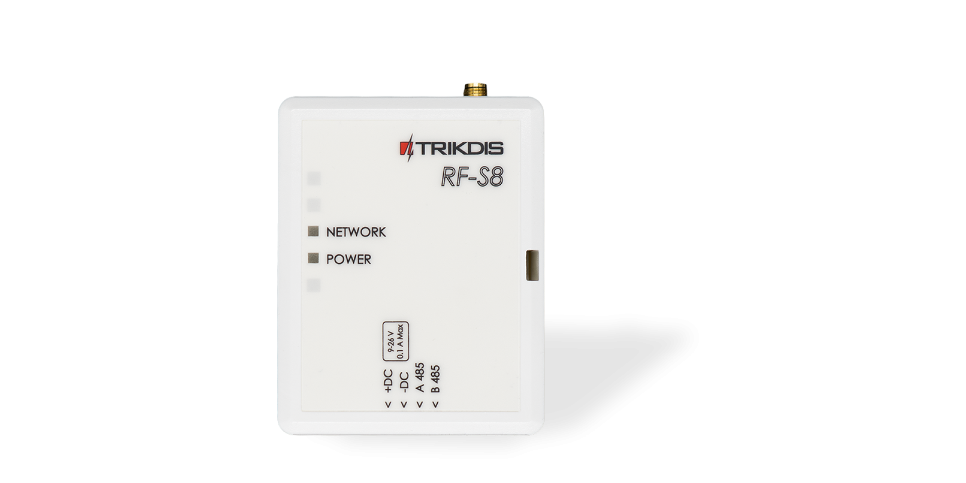
With the RF-S8 wireless transceiver (in TrikdisConfig: RF-S8 transceiver), the FLEXi SP3 alarm control panel works with the wireless detectors, sirens and remote controls of the S8 family. The RF-S8 is compatible with the FLEXi SP3 alarm control panel.
 Trikdis RF-S8 wireless receiver
- Radio range in open line of sight: up to 500 m.
- One RF-S8 can be connected to one FLEXi SP3.
- The product comes with a standard antenna that is suitable for most applications.
- The RF-S8 connects to the FLEXi SP3 via the RS485 bus.
1.2 The S8 devices
The S8 devices are members of the 868 MHz S8 radio family; they work with the FLEXi SP3 through the RF-S8 transceiver. Pairing them is described in chapter 4.
| Device | Item code | What it is for | Battery, power supply |
|---|---|---|---|
| PIR-Pet-S8 | S8-SPI | motion detector: dual-technology (dual-tech) PIR, viewing angle 110°, detection distance 12 m, pet immunity up to 35 kg | 2 × CR14505 lithium battery, 3 V (AA size), included |
| PIR-S8 | S8-SCP | curtain motion detector: curtain-type PIR, detection distance 9 m | 3 V DC |
| Magnet-S8 | S8-SDS | magnetic opening detector for doors and windows | 2 × CR2032 lithium coin cell, 3 V, included |
| Vibro-S8 | S8-SVS | vibration detector | – |
| Smoke-S8 | S8-SSA | smoke detector | 1 × CR17450 lithium battery, 3 V, included; lifetime up to 10 years |
| Flood-S8 | S8-SWL | water leak detector: detects leaked water with electrodes, its built-in sounder is louder than 90 dB | 2 × AAA battery, 3 V |
| SOS-S8 | S8-SEB | panic button | – |
| Keyfob-S8 | S8-SRC | keyfob remote control | 1 × CR2032 lithium coin cell, 3 V, included |
| Siren-S8 | S8-SFM | indoor siren (more than 100 dB at 1 m, adjustable volume) and signal repeater: relays the signal of distant detectors towards the panel; also works as a stand-alone alarm unit | 100–240 V AC, plugs directly into a mains socket |
| Siren-Outdoor-S8 | S8-SOS | outdoor siren | built-in 3.7 V, 5200 mAh Li-ion battery with solar charging; approx. 120 days of standby |
| Plug-S8 | S8-SSK | smart socket | – |
1.3 Technical data
| Parameter | Value |
|---|---|
| Supply voltage | 9–26 V DC |
| Current consumption | up to 50 mA in standby · up to 100 mA briefly, while transmitting |
| Radio frequency | 868 MHz |
| Transmitter power | 25 mW |
| Range | up to 500 m |
| Operating environment | −10 °C … +50 °C, relative humidity 80% (at +20 °C), non-condensing |
| Dimensions | 92 × 62 × 25 mm |
| Weight | 80 g |
The “up to … m” distances are theoretical maximums achievable under ideal conditions. In practice, the quality and routing of the cable, sources of interference and, for radio links, walls and terrain give a considerably shorter range. Plan with a margin, and on long runs check the connection during commissioning.
1.4 Parts
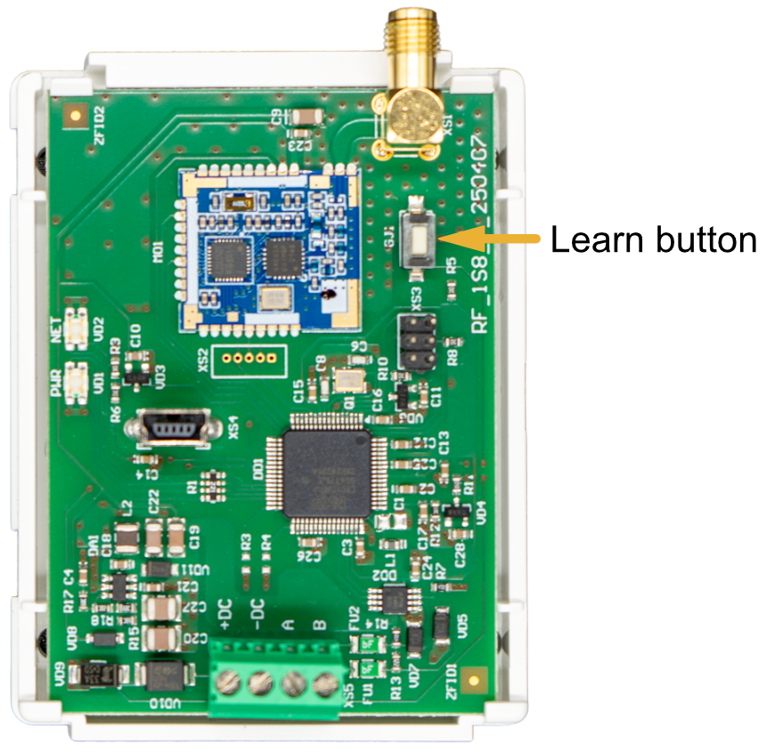
The connectors and controls of the RF-S8 are on the housing and on the printed circuit board:
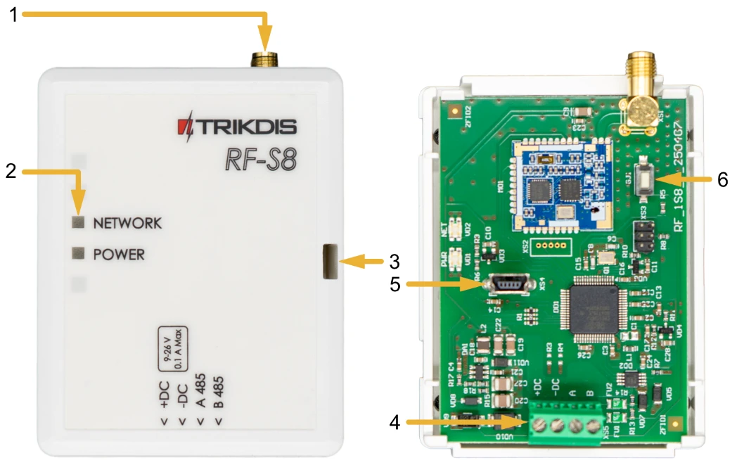
- 1 SMA connector for the radio antenna
- 2 indicators (NETWORK, POWER)
- 3 cover opening slot
- 4 terminal block for the external connections
- 5 USB Mini-B connector for updating the firmware
- 6 LEARN button – switches the learning (pairing) mode on and off
1.5 Terminals
The terminals for the external connections are on the printed circuit board; their labels are also visible on the front of the housing.
| Terminal | Function |
|---|---|
| +DC | supply voltage (9–26 V DC), positive |
| −DC | supply voltage (9–26 V DC), negative |
| A 485 | RS485 bus, A |
| B 485 | RS485 bus, B |

1.6 Indicators
Of the two indicators of the RF-S8, NETWORK shows the learning (pairing) mode, and POWER shows the supply voltage and the RS485 connection.
| Indicator | State | Meaning |
|---|---|---|
| NETWORK | flashes green and red | learning mode: detector pairing in progress |
| NETWORK | lights green for 5 seconds | in learning mode: a detector has been paired |
| POWER | off | no supply voltage |
| POWER | flashes green | normal supply voltage, normal operation |
| POWER | flashes yellow | low supply voltage (11.5 V or less) |
| POWER | lights yellow | no RS485 connection with the FLEXi SP3 |
On the board, the two indicators are labelled NET and PWR. Do not confuse them with the FLEXi SP3's indicators of the same name (NET, PWR): those are described in section 1.6 of the “FLEXi” SP3 alarm control panel – installation and programming manual.
2. Connecting to the FLEXi SP3
Warining!
It is forbidden to perform wiring on a device under voltage. Before starting the work, disconnect power (including backup batteries).Connect the RF-S8 to the RS485 bus of the FLEXi SP3; it also takes its power from the panel's AUX output:
| FLEXi SP3 | RF-S8 |
|---|---|
| AUX+ (+12 V) | +DC |
| AUX− | −DC |
| 485 A | A 485 |
| 485 B | B 485 |

- One RF-S8 can be connected to one FLEXi SP3.
- The RS485 bus can be up to 100 m long, and up to 8 devices can be connected to the bus.
- The current consumption of the RF-S8 is up to 100 mA. When sizing the backup battery, include the current consumption of the modules connected to the panel – the current calculation is described in section 2.1 of the “FLEXi” SP3 alarm control panel – installation and programming manual.
- The S8 devices only work with the panel's firmware with receiver code 4, version 1.22 or newer (SP3_xxx4_0122.fw). Changing the firmware and registering the RF-S8 are described in chapter 3.
3. The panel firmware
For the S8 devices, the FLEXi SP3 needs the firmware with receiver code 4, version 1.22 or newer (SP3_xxx4_0122.fw). Load the latest version: in November 2026 this is 1.27, with improved communication. When changing the firmware, the RF-S8 must be connected to the panel (chapter 2).
Which file to choose?
The firmware file name has the form SP3_yxxz_NNNN.fw. The digit y is the hardware version of the panel: only the file belonging to its own version can be loaded. The digit z is the type of wireless receiver, 4 for the RF-S8. NNNN is the version (0122 = 1.22). With the receiver code 4 firmware, the panel handles 64 zones, the RF-S8 (S8 devices) and the RF-LORA (MAXIMUM M4 devices) as wireless receivers, and the FLEXi and Paradox keypads as keypads. The list of modules that can be used with it is in section 1.7 of the “FLEXi” SP3 alarm control panel – installation and programming manual, and the rules for choosing are described in the article FLEXi SP3 firmware: how to choose the right one?.
3.1 Changing the firmware
All Trikdis devices can be programmed using a common software. The software is called TrikdisConfig and can be downloaded from the manufacturer's website.
After downloading, install the program. If a new version is available each time you start TrikdisConfig, download and install the recommended update!
- Connect the RF-S8 and the FLEXi SP3 according to the wiring diagram in chapter 2.
- Switch on the power supply of the FLEXi SP3.
- Start TrikdisConfig.
- Connect the FLEXi SP3 to the computer with a USB Mini-B cable.
- Open the Firmware window of TrikdisConfig.

- Click the Open firmware button and select the latest SP3_xxx4 firmware file (at least SP3_xxx4_0122.fw, the one for your panel's hardware version).
- Click the Update [F12] button.
- Wait until the update has finished.
- Unplug the USB Mini-B cable.
- Wait 1 minute.
- Plug the USB Mini-B cable back into the FLEXi SP3.
- In the TrikdisConfig status bar, the panel name (Device) must contain the digit 4.

3.2 Registering the RF-S8
After the firmware has been changed, the panel has to recognise the RF-S8. Leave the USB cable plugged in and continue as follows:
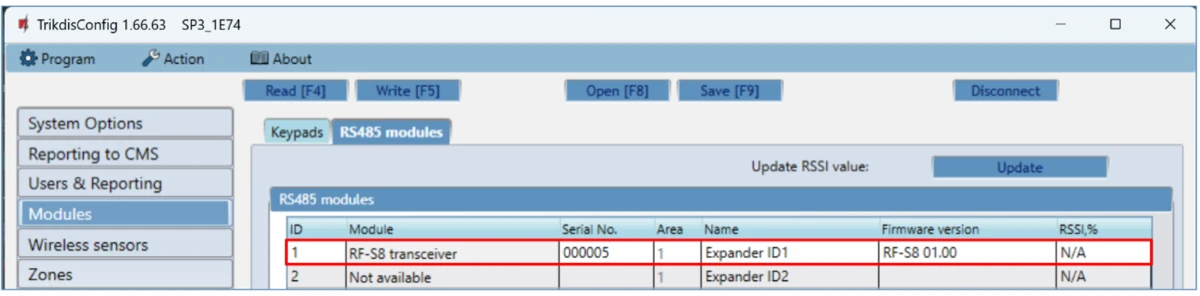
- Open the RS485 modules tab of the Modules window. The list must show the RF-S8 transceiver row with the serial number (Serial No.) and the firmware version (Firmware version). If you see the firmware version of the RF-S8, you can skip steps 2–10.
- If the list does not show the RF-S8 transceiver row, select the RF-S8 transceiver item from the list.
- Enter the serial number of the RF-S8 in the Serial No. field. You can find it on the device and on the sticker on the packaging.

- Click the Write [F5] button.
- Unplug the USB Mini-B cable.
- Wait 1 minute while the FLEXi SP3 and the RF-S8 connect.
- Plug the USB Mini-B cable back into the FLEXi SP3.
- Click the Read [F4] button.
- The firmware version of the RF-S8 appears in the Modules window, as in the figure for step 1.
- The RF-S8 is now connected to the FLEXi SP3.
- Unplug the USB Mini-B cable.
- Click the Disconnect button.

- Wait 1 minute.
While the USB cable is plugged into the Trikdis device (and the other end into the computer), the device switches to programming mode.
- Normal operation stops,
- It draws power from the USB cable,
- After unplugging, it restarts (if powered).
4. Pairing the detectors
You can pair the S8 devices – motion detectors, door and window opening detectors, smoke detectors, sirens, remote controls – with the FLEXi SP3 in four ways: with the Protegus 2 app (4.2), on the web.protegus.app web interface (4.3), remotely over the network with TrikdisConfig (4.4), or locally with the LEARN button of the RF-S8, without a network (4.5).
Every method requires that:
- the FLEXi SP3 runs the firmware with receiver code 4, version 1.22 or newer (SP3_xxx4_0122.fw, chapter 3);
- the RF-S8 is connected to the RS485 bus of the FLEXi SP3 (chapter 2) and registered in the Modules window of TrikdisConfig (3.2).
4.1 Preparation
Before pairing with any method, prepare the detectors:
- If the detector has previously been paired with any panel, first delete its pairing: press and hold its learning button for 5 seconds, and release it when its indicator flashes green three times. This deletes the detector's pairing. It is worth doing this for every detector before registration.
- Insert the batteries into all the detectors to be paired (motion detector, opening detector, water leak detector, smoke detector, siren). The power supply of the two sirens is described in the table in section 1.2.
- During pairing, the RF-S8 should be at least 1 m away from the detectors.
You can also pair all the detectors in one go.
Pairing and deletion
- You can pair the detectors with the panel, and you can also delete their pairing.
- Delete a detector's pairing only when the panel is not in detector learning mode. Do not pair or delete a detector while the panel is in learning mode because of another operation.
- If you accidentally delete a detector's pairing, the detector will not work with the panel until you pair it again.
4.2 Pairing with the Protegus 2 app
The Protegus 2 app must be installed on your phone, and the FLEXi SP3 system must be added to your account (see section 5.1 of the “FLEXi” SP3 alarm control panel – installation and programming manual).


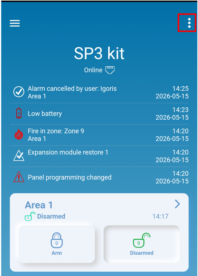
- Open the Protegus 2 app and select the FLEXi SP3 system (in the pictures: SP3 kit). Tap the ⋮ (three dots) button in the top right corner.
- Tap System configuration.

- Tap Devices.
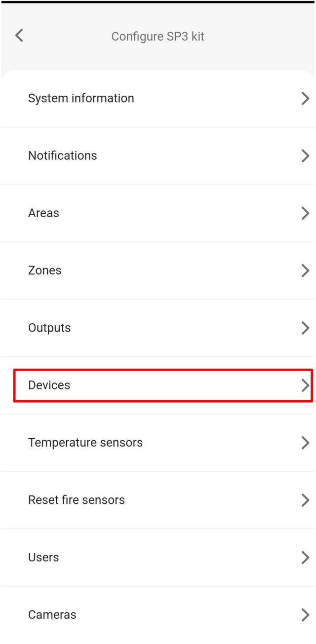
- To add a new detector, tap the + button.

- Select the type of the detector to be paired (for example Smart PET PIR detector – pet-immune PIR motion detector).

- In learning mode, the app shows the detector with a drawing marking the position of the learning button. Press and hold the detector's learning button until its green indicator lights steadily for 2 seconds.

- When the app finds the detector, it shows a confirmation with the detector's serial number. Tap OK.
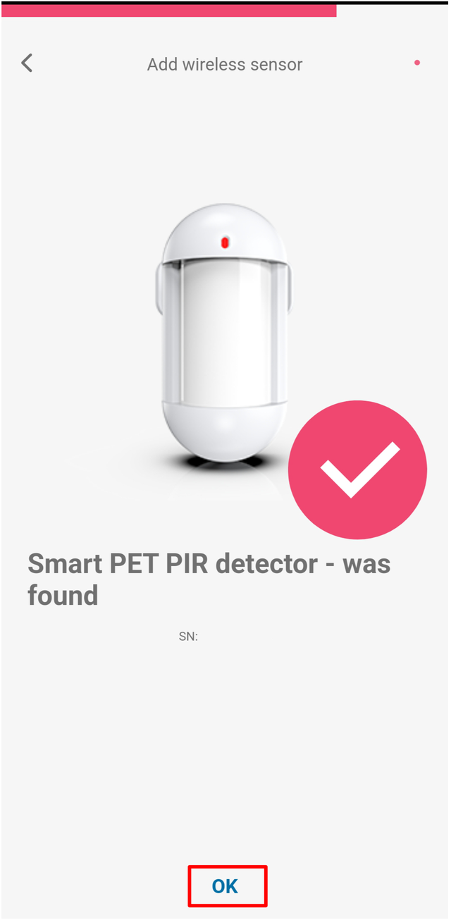
- The detector appears in the list with the NEW label. Tap it to open its settings.
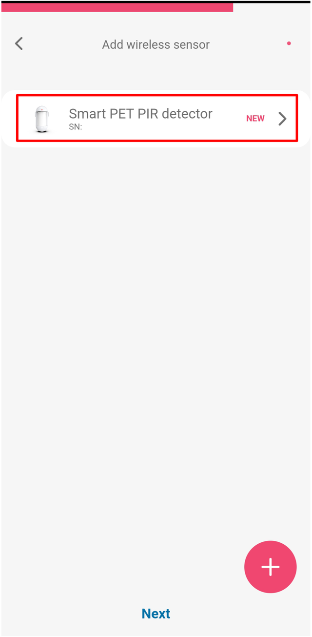
Zone settings:
- Tap the Zone settings section to expand it.
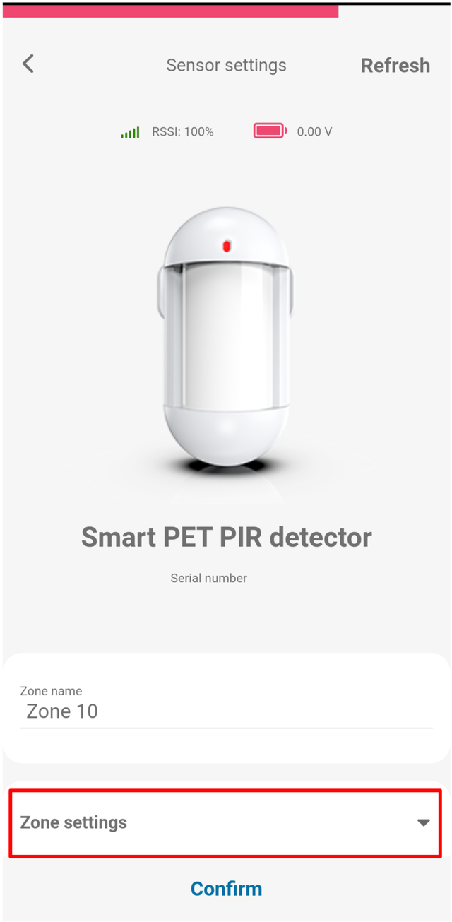
- Set the zone definition (Definition, for example 24 hours – 24-hour zone) and type (Type, for example NO – normally open), then tap Confirm.

- To add another detector, tap the + button and repeat steps 5–10. When you have paired all the detectors, tap Next.
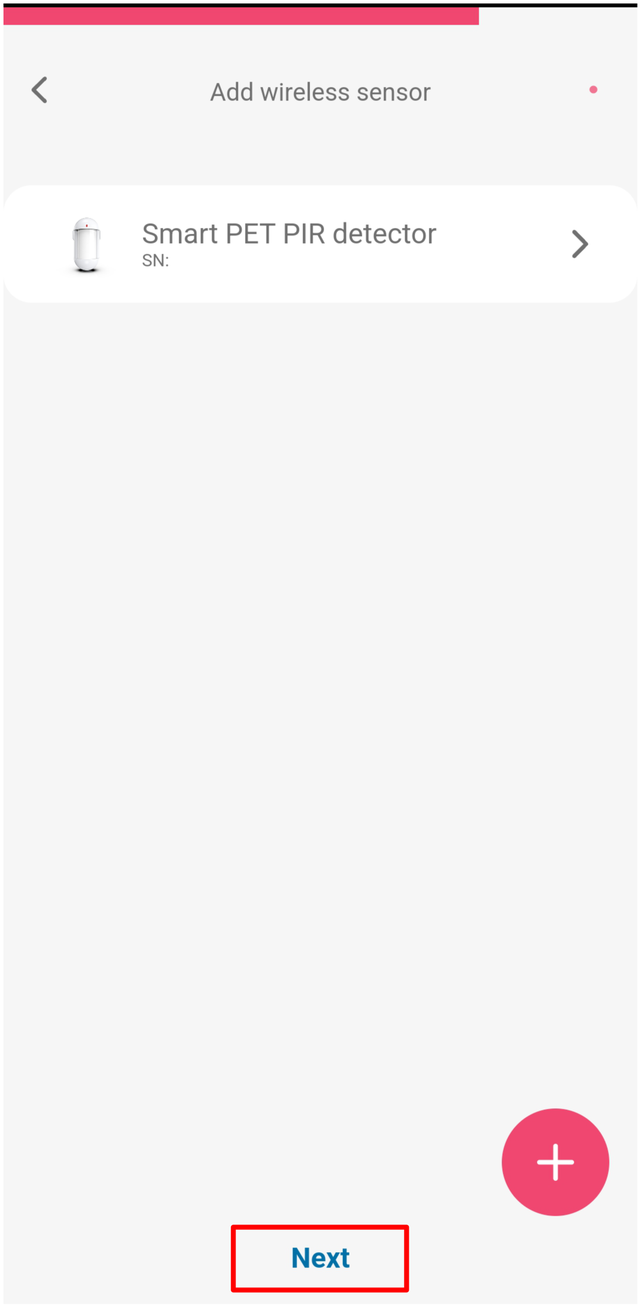
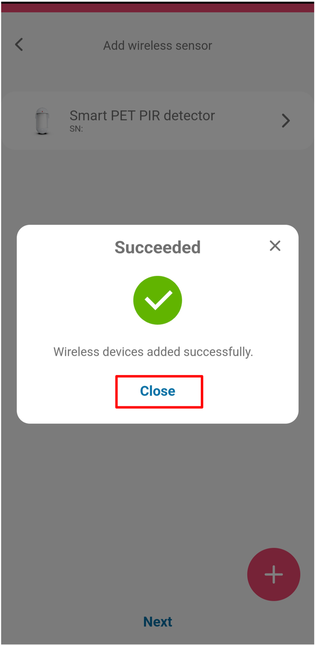
- A confirmation window shows that pairing was successful. Tap Close.
4.2.1 Zone states in the app
You can check the state of the paired detectors from the home screen of the system:
- On the home screen of the system, tap the Area 1 tile.

- Tap the Zone statuses button.

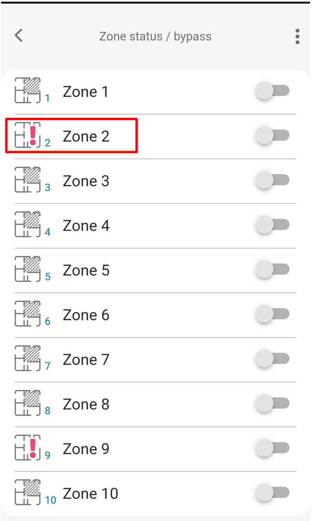
- The Zone status / bypass screen shows all zones. The red warning icon indicates that the detector is currently open or in alarm. With the bypass switches you can temporarily bypass individual zones.
4.3 Pairing on the web.protegus.app interface
Open web.protegus.app in a browser on a computer. The FLEXi SP3 system must be added to your account.
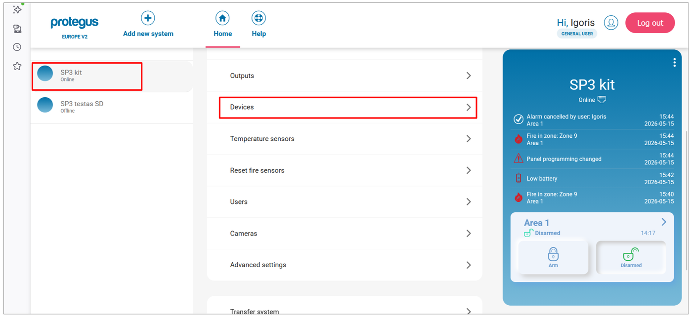
- In the left panel, select the FLEXi SP3 system, then click Devices in the system menu.
- To add a new wireless detector, click the + button.
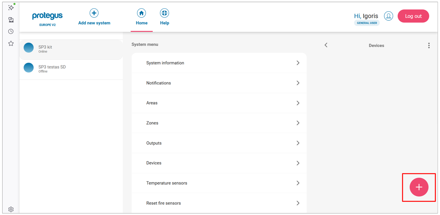
- The Add wireless sensor panel opens with the supported detector types. Click the type of the detector to be paired (for example Smart PET PIR detector).

- The interface switches to learning mode and shows the position of the detector's learning button in a drawing. Press and hold the learning button until the green indicator lights steadily for 2 seconds (this takes about 4–5 seconds).
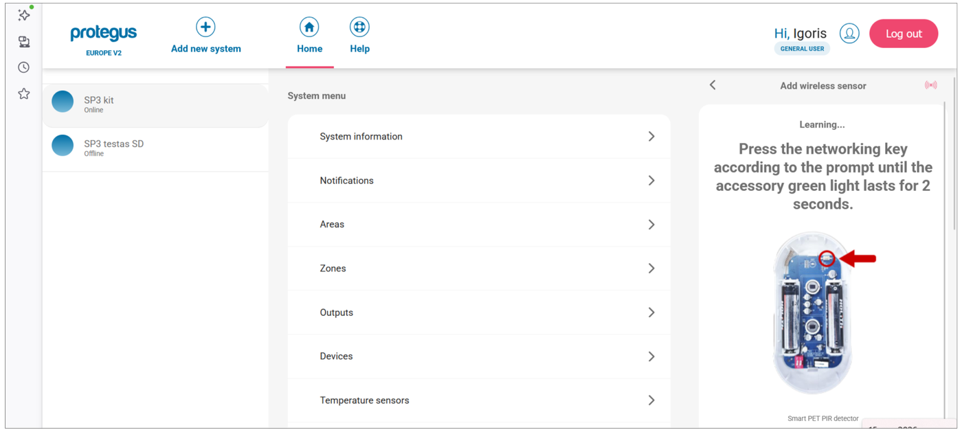
- When the panel finds the detector, a confirmation with the detector's serial number appears. Click OK.

- The detector appears in the list with the NEW label. To add another detector, click the + button and repeat steps 3–5. When you have paired all the detectors, click Next.
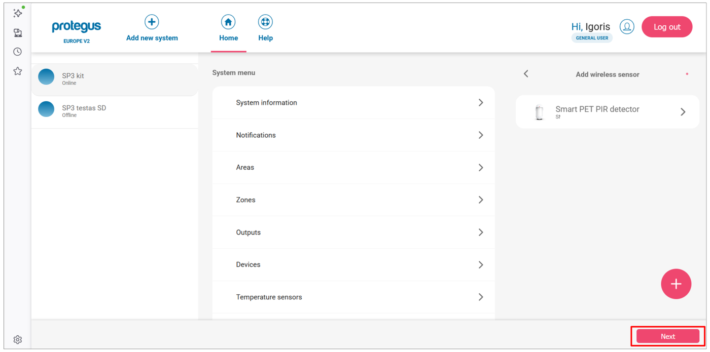
- A confirmation window shows that pairing was successful. Click Close.
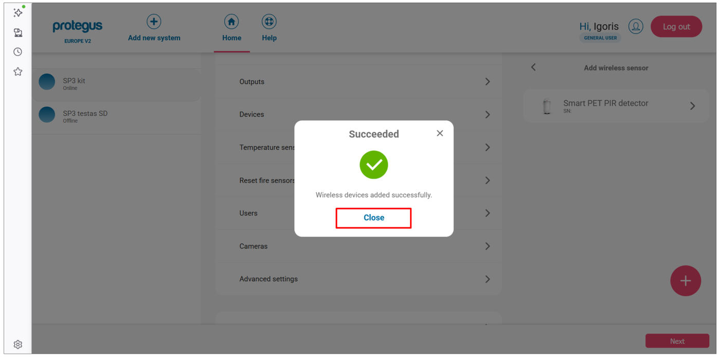
Zone settings:
- In the Devices list, click a paired detector to open its settings, then click the Zone settings section to expand it.
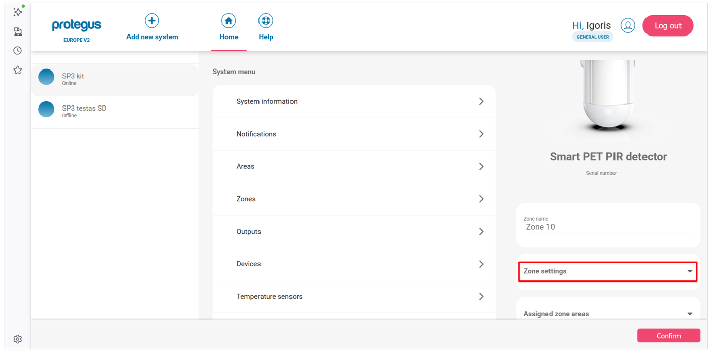
- Set the zone definition (Definition, for example Instant) and type (Type, for example NO – normally open), then click Confirm.

4.3.1 Zone states on the web interface
You can check the state of the paired detectors from the home screen of the system:
- On the home screen, click the Area 1 tile.
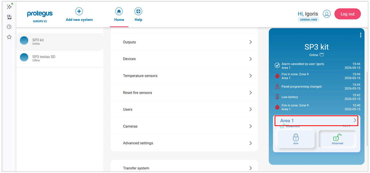
- Click the Zone statuses button.
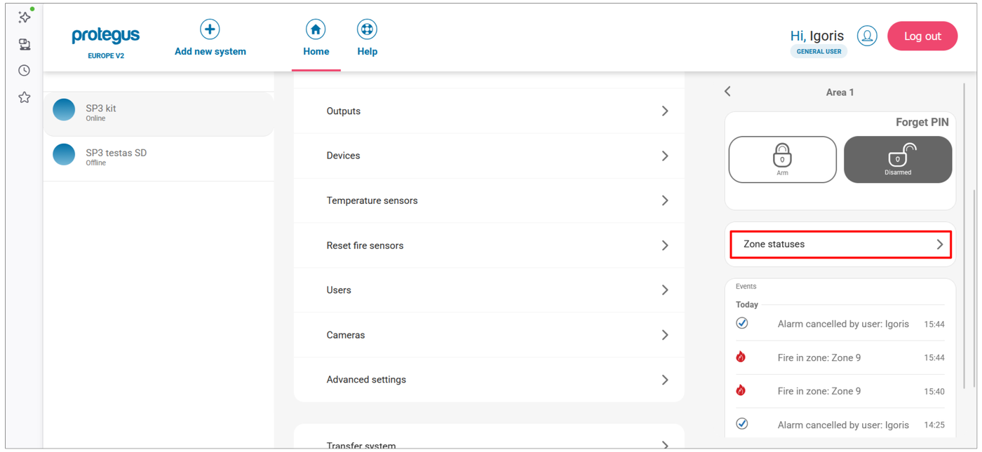
- The Zone status / bypass panel shows all zones. The red warning icon next to a zone indicates that the detector is currently open or in alarm. With the bypass switches you can temporarily bypass individual zones.

4.4 Pairing remotely with TrikdisConfig
With TrikdisConfig you connect to the FLEXi SP3 remotely, over the network. If there is no network connection, pair locally as described in section 4.5.
Requirements for remote configuration
- There is an activated SIM card in the FLEXi SP3, and its PIN code is entered or the PIN request is disabled.
- Mobile data is enabled on the SIM card.
- The Protegus cloud service is enabled: on the Protegus tab of the Users & Reporting window in TrikdisConfig, Enable cloud service is ticked (section 6.4.3 of the FLEXi SP3 manual).
- The panel is switched on: the PWR indicator of the FLEXi SP3 flashes green.
- The panel is connected to the network: the NET indicator of the FLEXi SP3 lights green and flashes yellow.
- On the TrikdisConfig start screen, in the Unique ID field of the Remote access group, enter the panel's IMEI/Unique ID number (unique identifier). You can find it on the panel and on the sticker on the packaging.
- Click the Configure button.
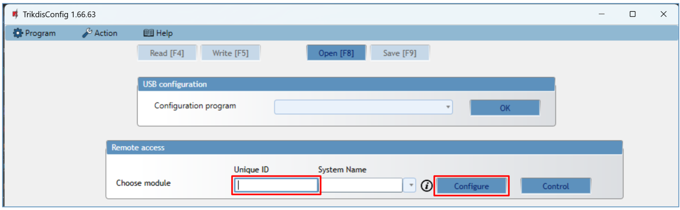
- In the window that opens, click the Read [F4] button. If the program asks for it, enter the administrator or installer code.
- Open the Wireless sensors window.
- Click the Learn sensors button.
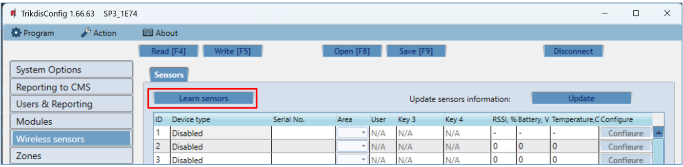
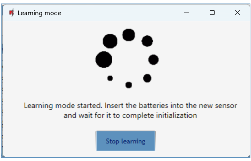
- The RF-S8 switches to learning mode: its NETWORK indicator flashes green and red, and TrikdisConfig opens the learning window (Learning mode).
- Press and hold the detector's learning button for 5 seconds. Release it when the detector's indicator flashes green four times.

- The NETWORK indicator of the RF-S8 turns green for a short time: the detector has been paired. After a few seconds it flashes green and red again.
- TrikdisConfig opens the New device was found window. Enter the zone number of the detector (Zone number) and the zone definition (Zone definition, for example Instant), then click Save.

- The detector is added to the list of detectors, and the status bar of the Learning mode window also shows its registration. For the next detector, press its learning button and repeat steps 7–9.
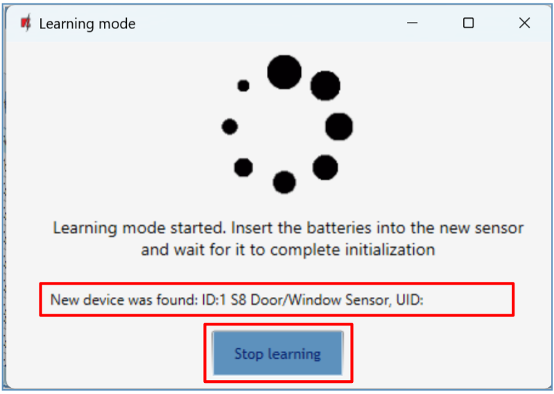
- Finish registering the detectors with the Stop learning button.
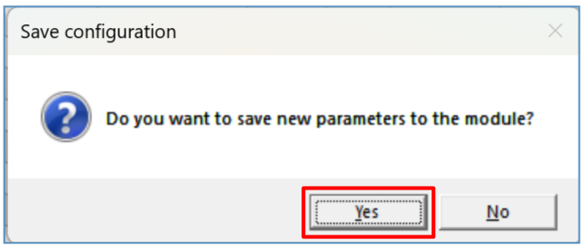
- When asked about saving, click Yes: the detectors are written to the FLEXi SP3. Choose No if you want to set further parameters first.
- Wait a few minutes, then click the Read [F4] button. The Wireless sensors window shows the list of registered detectors, with their serial numbers in the Serial No. column.

- In the Zones window, check that the detectors have been assigned to the correct zone and area (Area) of the panel. If the zone type (Type) is EOL_T, tamper monitoring of the detector is also enabled.

- After making changes, click the Write [F5] button.
4.5 Pairing locally with the LEARN button
There is a LEARN button on the printed circuit board of the RF-S8: with it you can start and stop learning mode without a computer, and no network connection is needed either. First carry out the preparation in section 4.1.
- Check that the RF-S8 is registered to the FLEXi SP3: it is visible in the TrikdisConfig Modules list (3.2).
- Switch on the power supply of the FLEXi SP3.
- Remove the cover of the RF-S8.
- Press and hold the LEARN button of the RF-S8 until the NETWORK indicator starts flashing green and red.
- Release the LEARN button.
- The flashing NETWORK indicator shows that the RF-S8 is in the registration (learning) mode for wireless devices.
- Press and hold the detector's learning button for 5 seconds. Release it when the detector's indicator flashes green four times (the position of the button is shown in the figure for step 7 of section 4.4).
- The NETWORK indicator of the RF-S8 lights steadily green for a short time: the detector has been paired.
- After a few seconds, the NETWORK indicator flashes green and red again.
- For the next detector, press its learning button (steps 7–9).
- To finish registration, press and hold the LEARN button until the green and red flashing of the NETWORK indicator stops, then release it. The RF-S8 has left registration mode.
- Connect the FLEXi SP3 to the computer with a USB Mini-B cable.
- Start TrikdisConfig and click the Read [F4] button.
- The Wireless sensors window shows the list of registered wireless devices, with their serial numbers in the Serial No. column (figure at step 13 of section 4.4).
- In the Zones window, check that the detectors have been assigned to the correct zone and area of the panel (figure at step 14 of section 4.4).
- After making changes, click the Write [F5] button.
- The detectors are registered.
4.6 Deleting a detector
This is how you delete a wireless detector from the memory of the FLEXi SP3:
- Start TrikdisConfig.
- Connect the FLEXi SP3 to the computer with a USB Mini-B cable, or connect to it remotely (4.4, steps 1–3). Click the Read [F4] button.
- In the Device type column of the Wireless sensors window, select Disabled instead of the detector to be deleted, then click the Write [F5] button. This deletes the detector from the memory of the FLEXi SP3.
5. Safety instructions
Attention!
Electricity can be dangerous and may cause personal injury or DEATH, as well as other financial loss or damage if not used or installed properly.
Installation involves working with electrical equipment, and it should be executed in accordance with current regulations!
Warranty validation requires the device to be installed by a qualified person following the installation regulations for electrical equipment and adhering to the current regulations for the safe operation of electrical equipment.
- The RF-S8 may only be installed and maintained by qualified persons.
- Before installation, read this manual carefully to avoid mistakes that can lead to malfunction or even damage to the equipment.
- Disconnect the power before making any connection.
- Changes, modifications or repairs not authorized by the manufacturer void the warranty.
- Do not throw the device and its parts in household waste: follow local waste sorting regulations.
See also
- “FLEXi” SP3 alarm control panel – installation and programming manual – wiring and setting up the panel: firmware versions (1.7), power supply and current consumption (2.1), adding the system to Protegus 2 (5.1), the Modules (6.5) and the Wireless sensors window (6.6).
- “FLEXi” SP3 alarm control panel – user manual – operating the system, the Protegus 2 app and the trouble indications.
- FLEXi SP3 firmware: how to choose the right one? – choosing the firmware file for the hardware version and the wireless receiver.
- Protegus Android / iPhone and web app – the Protegus 2 app and the web interface.
- Documentation: docs.trikdis.com – RF-S8 Wireless Transceiver and docs.trikdis.com – Adding S8 sensors to the FLEXi SP3.